Download
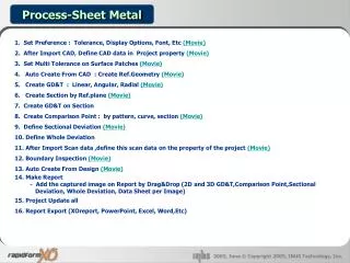
1 / 42
430 likes | 588 Vues
Variation Modeling and Design for Compliant Assemblies Prof. S. Jack Hu and Dr. K. Iyer Department of Mechanical Engineering and Applied Mechanics The University of Michigan. Compliant Sheet Metal Assembly. Variation Simulation Methods. Worst Case: (Conway, 1948; Chase and Parkinson, 1991)

E N D
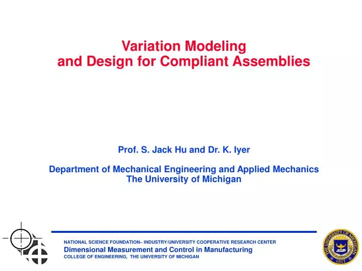
Variation Modelingand Design for Compliant AssembliesProf. S. Jack Hu and Dr. K. IyerDepartment of Mechanical Engineering and Applied MechanicsThe University of Michigan
Variation Simulation Methods Worst Case: (Conway, 1948; Chase and Parkinson, 1991) Root Sum Squares (RSS): (Spotts, 1978, Lee and Woo, 1990) Monte Carlo Simulation: (Craig, 1989)
Problem with Conventional Variation SimulationUsing Rigid Body Assumption N=64 (Takezawa, 1980)
Example of Variation Stackup
Introduction Type Rigid Body Assembly Compliant Assembly Properties B) Unique Properties of Compliant Assembly Assembly Examples PC Based Compliant Assembly Variation Analysis Assembly Mechanism Locating Principle Variation Propagation Geometry Closure Force & Geometry Closure “N-2-1” “3-2-1” Deformation and Spring-back Rigid-body Motion Assembly Characteristics
Understanding Variation “Stack-up” in Compliant Sheet Metal Assembly(Simple 1D model) Clamping forces Springback:
Part 1 10 1 100 Part 2 10 2 100 W h L (mm) same material Example When 1 and 2 are independent, Characteristics: (1) The assembly variation can be less than that of individual components, (2) The assembly variation is dominated by the variation of the more rigid component.
Compliant Assembly Variation Analysis (CAVA): Overview (Liu and Hu, 1997; Long and Hu, 1998)
Create model • Calculate • Evaluate • Modify the model CAVA Operating Procedures
Process for Sheet Metal Assembly The “3-2-1” fixture elements are closed The additional “N-3” clamps and weld guns are closed Welding. Then fixtures & clamps released, and sheet metal spring-back
Variation Characteristics in Sheet Metal Assembly (a) Rigid body motion by “3-2-1” fixture (b) Deformed part held by additional clamps and weld guns Va = [S1] Vp + [S2] Vt = [S] Vs (c) Spring-back after tooling release
R2 C RobustnessEvaluation Variation Transmission Ratio Sensitivity Index (Lee, Long and Hu; 2000) Robustness Index K = lN
Measure Variation Sources Node Dir. 41 37 63 233 247 255 313 309 335 505 519 527 274 2 0.5810 0.0245 0.0549 -0.1230 0.0088 0.1860 4.2300 -0.0473 0.4400 -0.8390 0.0130 1.2800 276 2 0.8090 -0.0859 0.0432 -0.0608 -0.0096 -0.0026 5.9000 -0.4340 0.3650 -0.5840 -0.0207 0.1420 309 2 0.2780 0.2130 0.2540 -0.0091 -0.0002 0.0090 2.1800 0.5550 2.0000 -0.0717 -0.0027 0.0717 498 2 -0.0026 -0.0096 -0.0608 0.0432 -0.0858 0.8090 0.1420 -0.0207 -0.5840 0.3650 -0.4340 5.9000 500 2 0.1860 0.0088 -0.1230 0.0549 0.0245 0.5810 1.2800 0.0130 -0.8390 0.4400 -0.0473 4.2300 519 2 0.0090 -0.0002 -0.0091 0.2540 0.2130 0.2780 0.0717 -0.0027 -0.0717 2.0000 0.5550 2.1800 CAVAApplications: Joint Design
Lap Joint Butt Joint Lap-Butt Joint K 8.56 27.61 11.98 Average Deviation (mm) 1.45 9.64 3.70 Joint Design: Robustness vs. Architecture 1) Parts variations are absorbed in lap joints 2) Parts variations are magnified in butt joints
Case # 1 2 3 4 Locations of clamps C1, C2, C3 C1, C2, C3, C4 C1, C2, C3, C5 C1, C2, C3, C4, C5 K 0.8465 0.8429 0.7536 0.7110 CAVAApplications: Fixture Configuration Design
Evolution of Variation and Stiffness (Hu, 1997)
Serial Line Configuration Parallel Line Configuration CAVAApplications: Assembly Line Configuration
Line Configuration Variation Single Assembly Station Serial Line Assembly
Robustness Kp Kt Station 1 0.9480 14.8973 Station 2 0.7007 0.2774 System 0.66 10.70 Line Configuration Robustness • Contributions of tooling and part variations can be different in • different stations and joint designs. • 2) A parallel configuration should be avoided with a station for which Kt > 1
Work Impact • A new methodology and variation simulation software, CAVA, has been developed which can be used to • Evaluate the dimensional capability of product architectures • Joint structure • The number and location of welds • Evaluate the dimensional capability of processes • Fixture schemes • Assembly sequence
Relevance Fatigue crack initiation Fretting Wear Leakage Electrical contact resistance …any situation where the integrity of a contact interface is important Assembly of Parts with Non-Flat Surfaces
2 1 Bolted Joint Model 1 3
32mm 16mm 24mm 16mm 2-D FEA of Surface Waviness • Abaqus software • Axisymmetric model plates (CAX4 elements) • Bolt in plane stress (CPS4 elements) • Bolt thickness (3-direction) varies to simulate circular cross section • Hole properties “smeared” • Sliding between plates possible • Stick conditions assumed at all bolt-plate interfaces
Contact Pressure and Gap Distributions I. II. IV. III.
Preliminary Indications • Joint compliance: • 176 mm/GN (II) > 30 mm/GN (IV) > 26 mm/GN (III) > 8.5 mm/GN (I) • Peak contact pressure, total gap and compliance are all related to each other. • Contact pressure distribution is non-“elliptical”. • Local bending at the contact surfaces is significant and affects the contact pressure and slip distributions. • Gap closure has may have a complex relationship to waviness • more wavy can mean more closure (compare III and IV) • Friction coefficient appears to have no effect on the contact pressure and slip distributions.
Shear Stress, Slip and Bulk Stresses I. II. III. IV.
Preliminary Parametric Study • Models I and IV considered • Material property change: steel vs. Al • T= 20 C,m= 0.4 • Temperature rise: 20 C 150 C • Al (material properties),m= 0.4 • Friction coefficient change:m=0 and 0.4 • Steel (material properties), T = 20 C
Effects of Material: Steel vs. Aluminum IV I IV I
Effect of material property: For perfectly flat contact, the effects on contact pressure and gap distribution are negligible For wavy contact, the total gap and maximum gap increase dramatically with decreasing material stiffness (Al) The machining tolerances applied to steel are not directly transferable to Aluminum Effect of temperature rise: Possibly complex alteration of the contact area, pressure and gap distributions in flat and wavy contacts Effect of friction coefficient: Does not alter contact pressure distribution Can affect the gap distribution if waviness is significant Inverse relationship with initial contact area indicated highermpromotes gap closure. Results
Increase in compliance with Al is ~ 3X: 8.5 mm/GN to 25 mm/GN in model I 30 mm/GN to 82.2 mm/GN in model IV Thermal springback: 539 mm/GN in model I (64.7 mm) 480 mm/GN in model IV (57.6 mm) Effect ofmon compliance is negligible Additional Results
A) Inclusion of gasket Solution for perfectly flat contact (model I) has been obtained. Modeling the highly localized, non-linear deformation of gasket material in the presence of surface waviness is currently receiving attention. Work in Progress Gasket
B) Multi-rivet joints effects of clamping sequence C) Closed-form solution for wavy contact P E2, n2 E1, n1