Download
1 / 30
300 likes | 427 Vues
Slides made by: Bin Wang. Team- W inning Team member: Bin Wang Erik Ware David Zigman Emile Bahdi. Bus tracker - Cdr. 2012 Capstone Senior design Colorado University at Boulder Instructor: Tom.Brown Sam.Siewert. Project Progress.

E N D
Slides made by: Bin Wang Team- Winning Team member: Bin Wang Erik Ware David Zigman Emile Bahdi Bus tracker - Cdr 2012 Capstone Senior design Colorado University at Boulder Instructor: Tom.BrownSam.Siewert
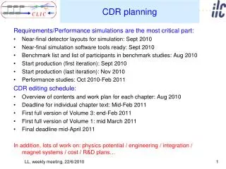
Project Progress • GPSmodule works and receives data using Arduino development board. • RF radio sends and receives data, acting like a 3000 foot serial cable. • Websitecan move data from mainstation hard drive to ECES sever, and upload to website in soft real-time. • PCB board is fully designed and ordering soon. Parts list is complete. • Finish a prototype design for the user station. Erik
Block diagram Tracker 9V Battery Cell Visual User Station GPS Server Terminal u-controller u-controller PC RX RF RS232 WiFi RX TX RF 9V, 1 amp Battery Cell Power Circuit Wi-Fi 9V backup Solar Cell RS232 Internet Website Erik
Update_file.sh SCP’s the data to the ECES server Write_file.pl script polls the serial port and saves the data to a data.txt file GPS data from satellite Data decoded by Atmel processor Atmel processor transmits using serial port and RF radio User station Wi-Fi module looks up data on ECES server and presents the data visually Data Flow Chart for Full Project Index.html on the ECES server presents the data online Data is received on the server through the RF radio eces.colorado.edu/~waree Erik
Software Description • Write_file.pl (perl) • Input: • Polls the serial port and saves GPS data received Output: data.txt file, this script also executes write_file.sh • User_station.c (C-code) • Input: • Looks up the GPS data on the ECES server and decoding it on the user-station processor; Output: visually displaying the data. • Update_file.sh (Expect) • Input: • data.txt file on computer HD; Output: The ECES server using SCP protocol. • GPS_software.c (C-code) • This is on the Atmel processor, Input GPS data received through the SPI connection to the GPS module. Outputs: sends data to the LCD screen and sends it through the RS-232 port to the RF radio. • Index.html (JavaScript/HTML/XML) • Handles the website JavaScript and html code, Input: looks up GPS data on ECES server; Output: display data on embedded Google map. Erik
Prototype of Tracking System RS232 9VCell AT:40.00726204LT:-105.26203 GSM Uctrler GPS LCD Bin
Software Decomposition LCD GPS- decode UART/RF Input: TTLsignal of ATLT Output: Uart signal in RS232 Bin
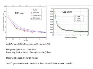
RF module Signal attenuate Significantly across building. Consistent high power consumption Bin
Small range: R = 0.6 km Large range: R = 1.4 km Bin
GSM(Global System for Mobile Communications) ADVANTAGE: “Infinite” working range 2. Guaranteed Communication Quality 3. Easy to control by u-ctrller than mobile phone itself. DISADVANTAGE: Mainance Fee.(<30$/month) Function: SMS text messages GSM/GPRS TCP/IP Cost: 50$/each Cellular-ADH8066 Bin
Power Design(tracker) 1.The power of GSM is 34 times lower than RF we used. 2.Reduce the power of the system by 40% 3.Sleep mode significant reduce the power consumption Bin
Functionality of the PCB Board • To transmit the current location to the receiver at the main station to be uploaded to the website Parts List • Atmega8-16PC • Voltage Regulators (NCP-1117-D, LP2985-33DBVR) • Serial Port • RS-232 (chip) • Clock (CSTCE16MOV53-R016MHz ) • LCD screen David
Microcontroller • The GPS module plugs directly into the PCB board and is controlled by the Atmega microcontroller. David
Powering the PCB Board • 9V battery plugs into the Power Jack • Voltage regulators convert the 9V battery input to 5V and 3.3V output • Green LED shows power is on David
Interface • The LCD screen will display the coordinates of the current bus location • The RS-232 boosts the signal to 10 V and outputs to the transmitter via the serial port David
PCB Layout David
Future Work on PCB Design • Thoroughly check the board layout before sending the layout to Advanced circuits • Order all the components from Digikey • Solder and mount components • Testing for Milestone 1 David
USER station • Display Bus Location • Time till bus arrive to the station
User station components • 10 W solar panel • LED map • Arduinouno • 74238 3- 8 decoder • LCD • WIFI-2.21 RN-131C • Rechargeable Battery Emile
Solar Battery Emile
User station Emile
Schematic View Emile
LED Screen Emile
Labor Division • Bin Wang • On-bus system and WiFi • Wireless communication and telephone application design. • David Zigman • On-bus PCB board design. • Erik Ware • Website design and working with David on PCB board and software. • Emile Bahdi • User station development. CTO CEO COO CFO
Picture Generated by Microsoft® Office Project 2007 Schedule & Time Management
Schedule and Milestones Finished Undergoing Jan.18 – Feb.2: Get group organized purchase essential hardware, get started and implement project detail plan. Feb.2 – Feb.28: Finish building a portable GPS device(Bin) Build the prototype of user station(Emile,Bin) Construct a website with CSS(Erik) Feb.28 – Mar.20: Communicate between terminal and server by WiFi-1(Bin) Design and build on-bus PCB(Dave,Erik) Design and build user-station(Emile,Bin) Update website with real-time data(Erik) Track main-campus bus without covering William Village and update website Mar.20 – Apr.10: Communicate between terminal and server by WiFi(Bin) Finish building user-station update data by WiFi(Emile,Bin) Embed website with Google Maps(Erik) PCB Board is working properly(Erik, David) Track whole bus route and update location to website and user-station. Apr.11 – Apr.30: Improve redesign and focus on user application and do commercial advertisement(Erik,David,Emile,Bin). Apri.30 – May2: Summarizing documents and prepare for expo. May3: Win (Team:Winning)
Budget: Total: 1091.1$ Remaining Fund:631.2$ (Note: some components can be obtained from Capstone Laboratory
Question and Discussion Your recommendation saves us money Your advice saves us time Presented by: Winning