Download
1 / 21
220 likes | 431 Vues
Packaging Design Roadmap. Fingerprint Sensor Mike Patterson November 2000. Contents. Current Design Comments on Current Design Other Design Options & Recommendations. Current Design Levels of Interconnect. Level 0: Athena Die to MEMS Substrate Flipchip

E N D
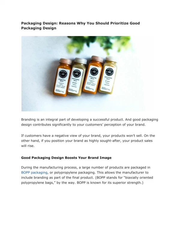
Packaging Design Roadmap Fingerprint Sensor Mike Patterson November 2000
Contents • Current Design • Comments on Current Design • Other Design Options & Recommendations
Current Design Levels of Interconnect • Level 0: Athena Die to MEMS Substrate • Flipchip • Level 1: MEMS Substrate to External • Flex Cable • Level 2: Substrate Assy to Backing Plate • Plastic? Metal? TBD • Level 3: Protective Bezel Housing
FLIPCHIP DIE FLEX CABLE MEMS SUBSTRATE FLIPCHIP DIE Current Design -Fingerprint Sensor Demonstration Module
Current Design Comments • Level 0 - Flip Chip • Silicon-to-Silicon or Silicon-to-Glass is Ideal for Reliability • No Thermal Mis-Match • No Underfill Requirements • This Allows Us to Consider Cost Effective Options Mainstream Products Wouldn’t Use • ACF • Electroless Nickel • Conductive Epoxy
Level 0 Assembly • Multiple Die & Substrate Format are Difficult to Assembly in a Traditional High Volume Semiconductor Assembly Factory • More Suited to Hybrid or Ceramic Line • Similar to Pentium Module w/Separate L2 Die?
MEMS Glass Substrate • Substrate Vendor will be expected to Singulate Substrates. • Substrates Delivered with Mylar Attached • Assume Substrates Shipped in Waffle Pak or QFP Type Tray Carriers
Higher Level Assembly • Flex Assembly to Backing Plate is Difficult to Automate • Reliability Concerns about Bezel and Backing Plate Stress on Substrate
Alternative Designs • Flip Chip in Pre-Molded Cavity • Improvement on Current Design • Tab / Chip-On-Glass • Similar to Flat Panel Display Assembly • Wire Bond MCM in BGA Package • High Volume Semiconductor Assembly
Proposed Cavity Solution WIREBOND I/O TO CONNECTOR EXTERNAL CONNECTOR MOLDED INTO HOUSING ATHENA DIE FLIP CHIP TO SUBSTRATE
Benefits of Cavity Design • Based on Design Currently in Production (Silicon Bandwidth) • Eliminates Flex Cable • Customer Could Provide Bezel • Improved Manufacturing Automation • Would Fit Typical Hybrid / Ceramic Process Flow
Proposed TAB Solution MEMS SENSOR ATHENA Athena Die Face Up
Benefits of TAB Design • Smaller MEMS Substrate (14x14 mm) • Pad Pitch on Substrate is 50µ • Typical of Today's Display Technology • Customer Provides Bezel • Much Thinner than Flip Chip Design (Height above sensor) • Con: Difficult to Mount Sensor Substrate
Manufacturing Benefits • Known Process in Display Industry • MEMS Substrate Supplier Could Supply Assembly Service (Japanese) • Easy to Automate • Test Athena Die Before Substrate Assembly • Saves Rework / Yield Loss of Expensive MEMS Substrate
Proposed Wire Bond Solution BGA Substrate 17 x 17 mm Die Face Up Epoxy Encapsulant
Benefits of Wire Bond Design • Smaller MEMS Substrate (14x14 mm) • Staggered Pad Pitch on Substrate is 100µ • Easy to Manufacture. Many Vendor Options. • Eliminates Flex Cable • Eliminates Flip Chip Process • Customer Provides Bezel • Thinner than Flip Chip Design (Height above sensor)
Manufacturing Benefits • Easy to Automate • Would Fit Amkor Process Flow (and Others) • http://www.amkor.com/assembly_and_test/products/bga/mcm-pbga/mcm-pbga.htm • Resultant Form Factor is Industry Standard • Shipping Trays • Test Sockets • Customer Assembly Knowledge (BGA) • Customer Saves Cost of Flex Connector • Customer Most Apt to Accept Reliability