Download
1 / 39
420 likes | 770 Vues
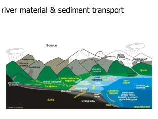
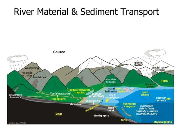
Sediment transport in wadi systems. Part 3 - Sediment management structures and canal design. phil.lawrence@sediment.plus.com. Summary sediment management strategy. Limit the diversion of coarser sediments Transport fine sediments through canals to the fields

E N D
Sediment transport in wadi systems Part 3 - Sediment management structures and canal design phil.lawrence@sediment.plus.com
Summary sediment management strategy • Limit the diversion of coarser sediments • Transport fine sediments through canals to the fields • Make provision for the inevitable rise in command levels
Limiting the diversion of coarser sediments • Locate intakes at outside of bends • Sediment excluding intakes • Limit diversion when wadi flows high –throttling structures or close gates • Secondary sediment control
Location of intakes at bends • The low flow channel carrying flood recession flows forms at the outside of a wadi bend. (Traditional intakes are placed at the outside of wadi bends for this reason.) • In floods bed load sweep will move the largest sediments towards the inside of a bend and away from an intake.
Traditional intake showing location at the outside of a wadi bend
Limiting the diversion of coarser sediments • Locate intakes at outside of bends • Sediment excluding intakes • Limit diversion when wadi flows high –throttling structures or close gates • Secondary sediment control
Features of the “spate” intake • No divide wall, flows can approach from any direction including parallel to the weir • Intake aligned to minimise the diversion angle • Curved channel with floor set lower than the intake gate sill encourages coarser sediments to move through the sluiceway • In this case a fuse plug was used
Limitations of sediment excluding intakes in spate schemes • Spate intakes divert all the wadi flows except for the short periods, sometimes only minutes, during flood peaks when wadi flows exceed the intake capacity. Sediment exclusion only effective during these periods. • Sluice gates have to be operated in response to rapidly varying spate flows – mechanised gates desirable but not often affordable.
Design of sediment excluding intakes -use of physical and numerical models • Physical models of practical scale overestimate sediment excluding performance - not always made clear in reports from modelling organisations • Numerical modelling has the potential to make quantitative predictions of sediment exclusion without problems in representing a wide range of grain sizes.
Simple intake model • The 3 d models described require considerable sediment transport and numerical modelling expertise to set up, calibrate, and run. • Simpler models are available that can be used to provide an indication of the sediment excluding performance of a basic intake. ( for example Sharc)
Example of output from simple model - impact of sluicing discharge
Limiting the diversion of coarser sediments • Locate intakes at outside of bends • Sediment excluding intakes • Limit diversion when wadi flows high –throttling structures or close gates • Secondary sediment control
Limit diversion from flood peaks • For simple un-gated intakes use flow throttling structures with a rejection spillway to limit the flows entering a canal. • For gated intakes consider closing canal gates during short periods of high flow. (There are problems of responding to rapidly varying flows, and farmers reluctance to “waste” water) Flow throttling structures with a rejection spillway are also used with gated intakes to ensure that canals are not damaged by excessive flows if the gates are left open during very large floods .
Limiting the diversion of coarser sediments • Locate intakes at outside of bends • Sediment excluding intakes • Limit diversion when wadi flows high –throttling structures or close gates • Secondary sediment control
Secondary sediment control • Settling basins • Canal sediment extractors
Models are used design settling basins/gravel traps Model predictions include: • Variation in sediment concentrations and grain sizes passing through a basin it fills with sediment. • Estimates of the frequency of sediment sluicing or de-silting operations. • The time period required to flush the basin and the volume of water needed for flushing. • The dimensions of an escape channel to convey sediment flushed from a basin to the river or disposal point.
Minimising trapping fine sediments A disadvantage of settling basins in spate schemes is their high trap efficiency for fine sediments at low flows or when basins are empty. To minimise the trap efficiency for fine sediments: • Basins should be relatively narrow, with sediment storage obtained by increasing the length, rather than the width or depth of the basin. • If it is considered necessary substantial reductions in the trap efficiency for fine sediments can be made if the tail water level in the basin is lowered for very low basin discharges. One possibility is to provide a notched weir at the basin exit, so that tail water levels are substantially lowered when the basin discharge is very low.
Secondary sediment control for spate schemes • Settling basins – Mechanically excavated or flushed basins can provide high sediment trap efficiencies with a low, or in the case of mechanically excavated basin, zero, “wastage” of water for sediment flushing. But sediment trap efficiency varies as a basin fills, and also with the basin discharge which varies from zero to full supply discharge in spate schemes. • Canal sediment extractors – Trap coarse sediment with a relatively constant trap efficiency but require continuous flushing flows of between 10% and 15 % of the canal discharge. Conventional extractors not suitable for use in spate schemes. • These disadvantages are minimised in the hybrid system shown on the next slide.
Hybrid extractor/flushed basin for large schemes • This system proved to be extremely successful in scheme in Philippines with massive sedimentation problems - halting, and then reversing, a long term decline in the irrigation service area, and providing very large economic returns.
Spate canal design methods • no scouring – no silting” criteria – not for spate • “Regime” design methods mostly for canals carrying low sediment loads but Simons and Albertson method include equations for canals with sand beds and cohesive banks, carrying “heavy” sediment loads – have been used in spate systems • Rational methods provide the most logical method of designing canals to achieve a specified sediment transporting capacity. Chang, 1985 method provides predictions of slopes and bed widths that are similar to that observed in many spate systems.
Comparison of predictions from Chang method with slopes measured slope of a wadi Zabid canal
Use canal surveys to aid design in modernised schemes • Canal designs in modernised schemes are best based on the slopes and cross sections of (stable) existing canals. Design of enlarged, extended or new canals can then be derived using the Chang equation, with a judicious choice of input parameters to provide a good match with the slopes and cross sections observed in existing canals.
Make provision for the inevitable rise in command levels • Rise rates 5 mm to more than 50 mm year observed in spate schemes • For existing schemes estimate historical rates of rise of fields from coring or trial pits, and the history of upstream movement of traditional diversion structures. • For new schemes base on command increase in near by systems • If no local information available base estimates on regional catchment sediment yield data, the proportion of the annual sediment load that will be diverted to a scheme, the scheme command area, a bulk density for settled silts, and the likely variation in sedimentation rates between upstream and downstream fields. (In wadi Laba in Eritrea mean sedimentation rates in upstream fields were about twice the mean rate for all fields.)