Download
1 / 24
240 likes | 421 Vues
ASME TURBO EXPO 20 10 , Glasgow, Scotland, UK. Dynamic Response of a Rotor-Hybrid Gas Bearing System due to Base Induced Periodic Motions. Luis San Andrés Mast-Childs Professor Fellow ASME. Yaying Niu Research Assistant. Keun Ryu Research Assistant. TURBOMACHINERY LABORATORY

E N D
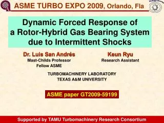
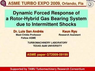
ASME TURBO EXPO 2010,Glasgow, Scotland, UK DynamicResponse of a Rotor-Hybrid Gas Bearing System due to Base Induced Periodic Motions Luis San Andrés Mast-Childs Professor Fellow ASME Yaying Niu Research Assistant Keun Ryu Research Assistant TURBOMACHINERY LABORATORY TEXAS A&M UNIVERSITY ASME paper GT2010-22277 Supported by TAMU Turbomachinery Research Consortium
Microturbomachinery (< 250 kW) Turbo Compressor 100 krpm, 10 kW Advantages • Compact and fewer parts • Portable • High energy density • Lower emissions • Low operation/maintenance costs http://www.hsturbo.de/en/produkte/turboverdichter.html Micro Turbo 500 krpm, 0.1~0.5 kW Oil-free turbocharger 120 krpm, 110 kW http://www.miti.cc/new_products.html http://www.hsturbo.de/en/produkte/micro-turbo.html
Gas bearings for microturbomachinery Advantages Metal Mesh Foil Bearing • Little friction and power losses • Simple configuration • High rotor speeds (DN value>4M) • Operate at extreme temperatures Issues • Small damping • Low static load capacity • Prone to instability GT 2009-59315 Gas Foil Bearing Flexure Pivot Bearing AIAA-2004-5720-984 GT 2004-53621
Gas Bearing Research at TAMU 2001/2 - Three Lobe Bearings 2003/4 - Rayleigh Step Bearings 2002-09 - Flexure Pivot Tilting Pad Bearings 2004-10:Bump-type Foil Bearings 2008-10:Metal Mesh Foil Bearings Stability depends on feed pressure. Stable to 80 krpm with 5 bar pressure Worst performance to date with grooved bearings Stable to 93 krpm w/o feed pressure. Operation to 100 krpm w/o problems. Easy to install and align. Industry standard. Reliable but costly. Models anchored to test data. Cheap technology. Still infant. Users needed
Objective & tasks Evaluate the reliability of rotor-air bearing systems to withstanding periodicbase or foundation excitations • Set up an electromagnetic shaker under the base of test rig to deliver periodic load excitations • Measure the rig acceleration and rotordynamicresponses due to shaker induced excitations • Model the rotor-air bearing system subject to base motions and compare predictions to test results
Rotor/motor Load cell Bearing Sensors Gas Bearing Test Rig Thrust pin Air supply Positioning Bolt 190 mm, 29 mm diam LOP Rotor: 826 grams Bearings: L= 30 mm, D=29 mm
Rotor and hybrid gas bearings Rotor • 0.826 kg, 190 mm in length • Location of sensors and bearings noted Flexure Pivot Hybrid Bearings:Improved stability, nopivot wear Clearance ~42 mm, preload ~40%.Web rotational stiffness = 62 Nm/rad. Test rig tilted by 10°.
Previous work (GT 2009-59199) Intermittent base shock load excitations Drop induced shocks ~30 g. Full recovery within ~ 0.1 sec. Ps=2.36 bar (ab) Rotor motion amplitudes increase with excitation of system natural frequency. NOT a rotordynamic instability!
Gas bearing test rig Base excitation Shaker & rod push base of test rig Front and side views (not to scale)
Hybrid gas bearing test rig Rod pushes base plate! (no rigid connection)
Waterfalls in coast down No base excitation Ps = 2.36 bar Subsynchronous whirl > 30 krpm, fixed at system natural frequency = 193 Hz
Rotor speed coast down tests (35 krpm) No base excitation 1X response Feed pressure increases natural frequency and lowers damping ratio Pressure 2.36bar 3.72bar 5.08bar Natural Freq 192Hz 217Hz 250Hz
Natural frequency whole test rig (5 Hz) Acceleration (g) Soft mounts (coils) produce low natural frequency
Delivered excitations (6 Hz) Rotor speed: 34 krpm (567 Hz) Acceleration (g) Acceleration (g) Acceleration (g) Due to electric motor zoom Shaker transfers impacts to rig base! Super harmonic frequencies excited
Waterfalls in coast down Shaker frequency: 12Hz Ps = 2.36 bar (ab)
Rotor speed coast down Shaker frequency: 12Hz Ps = 2.36 bar (ab) • Subsynchronous frequencies: • 24 Hz (2 x 12 Hz) • Natural frequency 193 Hz Synchronous motion dominates! Excitation of system natural frequency does NOT mean instability!
Effect of feed pressure Ps: 2.36, 3.72 & 5.08 bar Shaker frequency: 12Hz Rotor speed: 34 krpm (567 Hz) 12Hz, 24Hz, 36hz, etc NOT due to base motion! Pressure increases 243Hz 215Hz Offset by 0.01 mm 193Hz Rotor motion amplitude at system natural frequencydecreases as feed pressureincreases
Effect of rotor speed 26, 30 & 34 krpm Shaker frequency: 12Hz Feed pressure: 2.36 bar (ab) 12Hz, 24Hz, 36hz, etc Speed increases 193Hz 180Hz 180Hz Rotor motion amplitude at system natural frequencyincreases as rotor speed increases
Effect of base frequency 0, 5, 6, 9, 12 Hz Rotor speed: 34 krpm (567Hz) Feed pressure: 2.36 bar (ab) 193Hz Frequency increases NOT due to base motion! Rotor motion amplitude at natural frequencyincreases as excitation frequency increases
Rigid rotor model Rotor 1st elastic mode: 1,917 Hz (115 krpm) Equations of motion (linear system) U, Ub: rotor and base (abs) motions, Z=U-Ub M,G: rotor inertia and gyroscopic matrices W: rotor weight Fimb: imbalance “force” vector K, C: bearing stiffness and damping from gas bearing model (San Andres, 2006) Rework equations in terms of measured variables: System response = superposition of single frequency responses
Rigid rotor model Predicted natural frequencies Measured from 1X response tests Good agreement shows predicted bearing force coefficients are accurate For predictions: input RECORDED BASE accelerations (vertical)
Predictions vs. measurements Shaker input frequency: 12Hz Feed pressure: 2.36 bar (ab) Rotor speed: 34 krpm (567 Hz) Nat freq. 1X Excitation freqs. Above natural frequency, RBS is isolated! Predictions in good agreement! Test rotor-bearing system shows good isolation.
Conclusions Base Excitations on Gas-Rotor Bearing Syst • Rotor response contains 1X, excitation frequency (5-12 Hz) and its super harmonics and system natural frequency. • Rotor motion amplitudes at natural frequency are smaller than synchronous amplitudes. • Excited rotor motion amplitude at system natural frequency increases as gas bearing feed pressure(5.08~2.36bar) decreases, as rotor speed (26~34krpm) increases, and as the shaker input frequency (5~12 Hz) increases. • Predicted rotor motion responses obtained from rigid rotor model show good correlation with test data. Demonstrated isolation of rotor-air bearing system to withstand base excitations at low freqs.
Acknowledgments • Thanks support of • TAMU Turbomachinery Research Consortium • Bearings+ Co. (Houston) Learn more http://rotorlab.tamu.edu Questions ?