Download
1 / 41
520 likes | 1.41k Vues
PRIMARY SENSOR. Characteristic and types. Definition of a sensor. Def. 1. (Oxford dictionary) A device giving a signal for the detection or measurement of a physical property to which it responds. Def. 2.

E N D
PRIMARY SENSOR Characteristic and types
Definition of a sensor • Def. 1. (Oxford dictionary) • A device giving a signal for the detection or measurement of a physical property to which it responds. • Def. 2. • A sensor is a device that receives a signal or stimulus and response with an electrical signal.
Classification of sensors Attributes which can be used to classify sensors: . stimulus . working principle . properties (attributes of the characteristic) . application
Measurements Heisenberg (1927): ”The momentum and position of a particle can not both be precisely determined at the same time.” Measuring activity disturbs the physical process (loading effect). Measurement error: That is the difference between the measured value and the true value. error = measured value - true value Deterministic errors: They are repeated at every measurement, e.g. reading offset or bias. Such errors can be corrected by calibration. Random errors: They are caused by several parameters and change in time in an unpredictable fashion. They can be quantified by mean errors, standard deviation. Precision: Measurements with small deviation Accuracy: Measurements with small errors, i.e. small bias and high precision.
Sensor properties output factual ideal input A sensor should represent a physical variable as fast and as accurately as possible. A sensor is represented by its characteristic. Ideally, the sensor characteristic is a straight line
SENSOR CHARACTERISTIC • Full scale input (input span) • A range of stimuli that can be converted by one sensor. • Full scale output (output span) • Full scale output is the algebraic difference between the output signals measured with maximum input stimulus and with minimum input stimulus applied.
SENSOR CHARACTERISTIC Accuracy : Error measurement Sensitivity: change in output for unit change in input Resolution: the smallest change in the signal that can be detected and accurately indicated by a sensor. Linearity: the closeness of the calibration curve to a straight line. Drift: the deviation from the null reading of the sensor when the value is kept constant for a long time.
SENSOR CHARACTERISTIC Hysteresis: the indicated value depends on direction of the test (increasing and decreasing) Repeatability (precision): the maximum deviation from the average of repeated measurements of the same static variable. Dynamic Characteristics: A sensor may have some transient characteristic. The sensor can be tested by a step response where the sensor output is recorded for a sudden change of the physical variable. The rise time, delay time, peak time, settling time, percentage overshoot should be as small as possible.
Motion sensors • These transducers measure the following variables: displacement, velocity, acceleration, force, and stress. • Such measurements are used in mechanical equipment such as servo-systems, robots, and electrical drive systems. • Motion sensors include the following types of devices: potentiometers, resolvers, optical encoders, variable inductance sensors (displacement), tachometers (velocity), piezo-resistive sensors (strain).
Resolver • Resolvers are used in accurate servo and robot systems to measure angular displacement. Their signal can be differentiated to obtain the velocity. • The rotor is connected with the rotating object and contains a primary coil supplied by an alternating current from a source voltage vref. The stator consists of two windings separated by 90o, with induced voltages V01= K vref sin θ V02= K vref sin θ
Tachometer • The permanent magnet generates a steady and uniform magnetic field. Relative • motion between the field and the rotor induces voltages, which is proportional • to the speed of the rotor. • The inductance gives the tachometer a certain time constant so that the • tachometer cannot measure fast transient accurately.
Optical encoders • These are optical devices to measure angular displacement and angular velocity. • A disk of an optical encoder is connected to the rotating shaft. • The disk has patterns (holes). • On one side of the disk there is a light source and on the other photo-detectors. When the disk rotates the light is going through the holes and the photo-detectors generate series of pulses. • There are two types of optical encoders: incremental and absolute.
Optical encoders • The incremental encoder provides a pulse each time the shaft has rotated a defined distance. • The disc of an absolute encoder has several concentric tracks, with each track having an independent light source and photo detector. • With this arrangement a unique binary or Gray coded number can be produced for every shaft position.
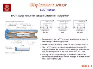
Vout displacement LVDT • The two secondary coils are connected in the opposite phase. When the core is in the middle there is no output voltage. • Moving the core from the central position unbalances the secondaries, developing an output. Applications: • To measure linear displacement, e.g. for measuring tube lengths in a steel plant, • applied in linear servomechanisms, etc.
Strain gauge • When external forces are applied to a stationary object, stress and strain are the result. • Stress is defined as
Strain gauge • Strain is defined as the amount of deformation per unit length of an object when a load is applied. Strain (ε) = ΔL/L • Typical values for strain are less than 0.005 inch/inch and are often expressed in micro-strain units: 1 μstrain = 106 strain
Strain gauge • Strain may be compressive or tensile and is typically measured by strain gages. • It was Lord Kelvin who first reported in 1856 that metallic conductors subjected to mechanical strain exhibit a change in their electrical resistance. • This phenomenon was first put to practical use in the 1930s.
Strain gauge • Fundamentally, all strain gages are designed to convert mechanical motion into an electronic signal. • A change in capacitance, inductance, or resistance is proportional to the strain experienced by the sensor.
Strain gauge • If a wire is held under tension, it gets slightly longer and its cross-sectional area is reduced. This changes its resistance (R) in proportion to the strain sensitivity (S) of the wire's resistance. When a strain is introduced, the strain sensitivity, which is also called the gage factor (GF), is given by: GF = (ΔR/R)/(ΔL/L)
Strain gauge • The ideal strain gage would change resistance only due to the deformations of the surface to which the sensor is attached. • However, in real applications, temperature, material properties, the adhesive that bonds the gage to the surface, and the stability of the metal all affect the detected resistance.
Strain gauge • Because most materials do not have the same properties in all directions, a knowledge of the axial strain alone is insufficient for a complete analysis. Poisson, bending, and torsion strains also need to be measured. Each requires a different strain gage arrangement.
Strain gauge • The deformation of an object can be measured by mechanical, optical, acoustical, pneumatic, and electrical means. • The earliest strain gages were mechanical devices that measured strain by measuring the change in length and comparing it to the original length of the object.
Strain gauge • The most widely used characteristic that varies in proportion to strain is electrical resistance. Although capacitance and inductance-based strain gages have been constructed, these devices' sensitivity to vibration, their mounting requirements, and circuit complexity have limited their application. • The photoelectric gage uses a light beam, two fine gratings, and a photocell detector to generate an electrical current that is proportional to strain. The gage length of these devices can be as short as 1/16 inch, but they are costly and delicate.
Strain gauge • The first bonded, metallic wire-type strain gage was developed in 1938. The metallic foil-type strain gage consists of a grid of wire filament (a resistor) of approximately 0.001 in. (0.025 mm) thickness, bonded directly to the strained surface by a thin layer of epoxy resin
Application of Strain gauge • Strain gages are used to measure displacement, force, load, pressure, torque or weight. Modern strain-gage transducers usually employ a grid of four strain elements electrically connected to form a Wheatstone bridge measuring circuit. • The strain-gage sensor is one of the most widely used means of load, weight, and force detection. • As the force is applied, the support column experiences elastic deformation and changes the electrical resistance of each strain gage. By the use of a Wheatstone bridge, the value of the load can be measured. Load cells are popular weighing elements for tanks and silos and have proven accurate in many other weighing applications.
Application of Strain gauge • Strain gages may be bonded to cantilever springs to measure the force of bending. • The strain gages mounted on the top of the beam experience tension, while the strain gages on the bottom experience compression. The transducers are wired in a Wheatstone circuit and are used to determine the amount of force applied to the beam.
Application of Strain gauge • Strain-gage elements also are used widely in the design of industrial pressure transmitters. Using a bellows type pressure sensor in which the reference pressure is sealed inside the bellows on the right, while the other bellows is exposed to the process pressure. • When there is a difference between the two pressures, the strain detector elements bonded to the cantilever beam measure the resulting compressive or tensile forces.
Application of Strain gauge • A diaphragm-type pressure transducer is created when four strain gages are attached to a diaphragm. • When the process pressure is applied to the diaphragm, the two central gage elements are subjected to tension, while the two gages at the edges are subjected to compression. • The corresponding changes in resistance are a measure of the process pressure. When all of the strain gages are subjected to the same temperature, such as in this design, errors due to operating temperature variations are reduced.
Piezoelectric Materials • Many polymers, ceramics, and molecules such as water are permanently polarized: some parts of the molecule are positively charged, while other parts of the molecule are negatively charged.
Piezoelectric Materials • When an electric field is applied to these materials, these polarized molecules will align themselves with the electric field, resulting in induced dipoles within the molecular or crystal structure of the material.
Piezoelectric Materials Furthermore, a permanently-polarized material such as quartz (SiO2) or barium titanate (BaTiO3) will produce an electric field when the material changes dimensions as a result of an imposed mechanical force. These materials are piezoelectric, and this phenomenon is known as the piezoelectric effect.
Piezoelectric Materials • Conversely, an applied electric field can cause a piezoelectric material to change dimensions. • This phenomenon is known as electrostriction, or the reverse piezoelectric effect. • Piezoelectric Effect Reverse Piezoelectric Effect
Piezoelectric Materials • Piezoelectric materials are used in acoustic transducers, which convert acoustic (sound) waves into electric fields, and electric fields into acoustic waves. Transducers are found in telephones, stereo music systems, and musical instruments such as guitars and drums.
Piezoelectric Materials • Quartz, a piezoelectric material, is often found in clocks and watches. An oscillating electric field makes the quartz crystal resonate at its natural frequency. The vibrations of this frequency are counted and are used to keep the clock or watch on time. • A manufacturer has recently embedded piezoelectric materials in skis in order to damp out the vibrations of the skis and help keep the ski edges in contact with the snow.