Download
1 / 40
400 likes | 410 Vues
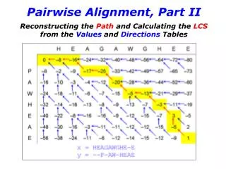
Chapter 6 View Alignment Techniques and Method Customization (Part II). Object-Oriented Technology From Diagram to Code with Visual Paradigm for UML Curtis H.K. Tsang, Clarence S.W. Lau and Y.K. Leung McGraw-Hill Education (Asia), 2005. View Alignment Techniques (VAT).

E N D
Chapter 6View Alignment Techniques and Method Customization(Part II) Object-Oriented Technology From Diagram to Code with Visual Paradigm for UML Curtis H.K. Tsang, Clarence S.W. Lau and Y.K. Leung McGraw-Hill Education (Asia), 2005
View Alignment Techniques (VAT) • We can summarize the characteristics of software models as follows: • Models can have different levels of abstraction. • A model focuses on the one aspect of a problem that we are interested in. • Elements of a model are often represented in different ways as parts of other models. • The most basic and extremely important principles of software engineering are composiblity and decomposability.
View Alignment Techniques (cont’d) • We decompose in order to understand (a problem) and compose in order to build (a system). • When we have developed models which describe the different perspectives of the system, we should ultimately be able to form a complete and consistent picture of the system. This is the basic idea of the View Alignment Techniques. • For example, given the different elevations of a building’s floor plan, we can mentally create a 3D model of the building.
Basic Ideas • View Alignment Techniques are particularly applicable to software modeling and analysis because they can help us discover what models are required for the entire development life cycle methodically. • The designer could start with a model depending on the readily available information and then develop other related models by applying the View Alignment Techniques.
Basic Ideas (cont’d) • A software model usually emphasizes on a particular aspect (strong view) of the system together with one or more aspects (weak views) of the system. • Two models can be linked when a weak view of one model is the strong view of the other model. • For example, an element may form a part of two or more models and provides the common view (i.e. static or dynamic) of the system. • In our terminologies, such an element is called a linked element.
Example – Sequence Diagram and Class Diagram Linked Elements SequenceDiagram Class Diagram
Principles of View Alignment Techniques • The underlying principles of the View Alignment Techniques are based on the identification of linkages among models by applying three model manipulators at three different levels of the development workflows. • The three model manipulators are called Model Elaborator, Model Transitor and View Aligner. • The manipulators can be used to help in conducting modeling and analysis throughout the entire development process.
Principles of View Alignment Techniques (cont’d) • Each of these manipulators can be applied to three different levels which are: within, between and among the workflows, such as Business Modeling, Requirements, Analysis, Design, and so on. • For example, you normally apply a model elaborator within one of the above workflows and a model transitor to derive the Requirements workflow that is based on the Business Modeling workflow. • Finally, a view aligner manipulator is used to ensure models consistency as artifacts have been created in the development iteration.
Manipulators • A model elaborator is used to elaborate a source model (or its element) by providing additional information to produce a more detailed, sub-level model. The applications of a model elaborator should normally take place within a workflow. • For example, a use case can be elaborated by an activity diagram and a use case description. • Model elaborators provide traceability through the detailed representation of models in different levels of abstraction.
Manipulators (cont’d) • A model transitor manipulator is used to discover the requirements of a target model based on the linked elements identified in the source model. • While the target model and the source model focus on different aspects of the system, there exist some linked elements, sharing a common view, in both the target and source models. • A model transitor is normally used when a workflow has fully been explored, and at that point, you want to move on to the next workflow of the development process.
Manipulators (cont’d) • A view aligner manipulator is used to establish points of connection among different models. • The connections among models can help us identify the things that need to be updated in one model when the linked elements of another model have changed. • The view aligner is normally applied iteratively upon the completion of a new workflow.
The Grammar of Model Manipulators • <model relationship> ::= <model manipulator> ‘(‘ <parameter list> ‘) | <parameter> <operator> <parameter> • <operator> :: = ‘->’, ‘=>, ‘’ • <model manipulator> ::= ‘elaborator’ | ‘transitor’ | ‘aligner’ • <parameter list> ::= <parameter> | <parameter> ‘,’ <parameter list> • <parameter> ::= <model> | <model> ‘[‘ <version> ‘]’ | <model> ‘.’ <element list> | <model> ‘[‘ <version> ‘]’ ‘.’ <element list>
The Grammar of Model Manipulators (cont’d) • <element list> ::= <element> | ‘{‘ <elements> ‘}’ • <elements> ::= <element> | <element> ‘,’ <elements> • <element> ::= “a part of a model” | <element> ‘.’ <element list> • <model> ::= “a model, a diagram, an entity, or an artifact used for modeling a system” • <version> ::= “the version”
Examples of Model Manipulators • elaborator (use_case_A, use_case_description_B) or use_case_A -> use_case_description_B means the second model, use case description, is an elaboration of the first model, a use case. • use_case_A -> use_case_description_B => activity_diagram_C means that we use an elaborator to develop the use case description and then apply a transitor to develop an activity diagram.
Example - Data Dictionary to Use Case Diagram • Transitor(data_dictionary.{use_case_list, actor_list}, use_case_diagram) or • data_dictionary.{use_case_list, actor_list} => use_case_diagram
Example - Textual Analysis • Transitor(problem_statement[use case level], use_case_list) or • problem_statement[use case level] => use_case_list
Example - Specification of Workflow • Transitor(use_case_description[requirement workflow].flow_of_event, activity_diagram) or • use_case_description[requirement workflow].flow_of_event => activity_diagram.action_state_list
Example - Simple View Aligner • sequence_diagram.object_list class diagram.class_list
Example - Points of Connection for Multiple Models • sequence_diagram.object_list collaboration_diagram.object_list class_diagram.class_list
Applying View Alignment Techniques (VAT) • The View Alignment Techniques equip designers with the ability to create new or customize existing software development methods. • In the case of method creation, View Alignment Techniques can help the designer to select suitable models out of the rich set of UML notations for different workflows in the development process. • For customizing an existing method to suit the specific needs of an organization, the View Alignment Techniques can provide guidance and hints when the existing method does not seem to work well.
Applying View Alignment Techniques (cont’d) • Developing a new software method is in many respects analogous to playing a detective role, investigating and solving a crime. • There are no fixed procedures or heuristics to start the investigation, as each crime generally has its own unique circumstances, and all relevant facts will have to be considered as they are uncovered. • Nonetheless, the detective would logically start from a point or area where he can quickly gather clues or evidence about the crime.
Applying View Alignment Techniques (cont’d) • The strategy here would be to uncover as many relevant facts as quickly as possible. • Sometimes, a detective may get stuck and seem to get nowhere on a lead. • It would be natural for him to move on to other areas to dig deeper. • But as more facts and evidences are unveiled, the detective would try to consolidate and put the bits and pieces together to get a global perspective of the situation.
Applying View Alignment Techniques (cont’d) • In applying the View Alignment Techniques, we do not adhere to a fixed set of procedures, techniques or models. • Instead, we only need to have a rough plan. • The View Alignment Techniques can help us design or customize our own process as we discover more details of the system. • We typically start with the most suitable or convenient model where we have a lot of information about the system and then develop other models by applying the appropriate manipulators.
Applying View Alignment Techniques (cont’d) • Ultimately, the view alignment techniques will guide us through the necessary and relevant models of the system. The following seven steps describe how the View Alignment Techniques should be applied. • Configure the Process • Select Models for the Workflow under development • Apply Model Elaborators • Identify Linked Elements • Apply Model Transitors • Apply View Aligners • Update Linked Element for the Related Models
Step 1: Configure the Unified Process • The predefined workflows in an iteration of the Unified Process are Business Modeling, Requirements, Analysis, Design, etc. Some problems may involve only isolated tasks which do not have many connections with the business operation. • In such situations, the business modelingworkflow may be optionally removed from the development iteration or even the whole process. Some developers may want to include the workflow up to Design workflow while others may want to include Implementation, Testing and so on. • In this step, you configure the standard workflows and the number of iterations involved in each development phase.
Step 2: Select Models into the Workflows • With the View Alignment Techniques, the designer should first consider the amount of information that is readily available and then select the most convenient model for development. • Systems handling business activities => Use case, activity diagram. • Parser => Grammar rules • Algorithm intensive application => Textual analysis, CRC
Step 2: Select Models into the Workflows (cont’d) • The procedure for this step is as follows: • Consider the aim and objective of the workflow in the context of the information on hand to select the appropriate models to start with. • Determine the strong view of the main model you have selected, given the nature of the workflow being developed.
Step 3: Apply the Model Elaborator to Complete the Workflow • We usually determine the strong view based on the nature of the workflow being developed. • For example, Business Modeling is often represented by an activity diagram for modeling a business workflow.
Step 3: Apply the Model Elaborator to Complete the Workflow (cont’d) • The procedure for this step is as follows: • Determine the strong view of the next workflow. If you can identify the linked elements from the main model straight away for the next workflow, then mark them down for discovering the requirements for the models of the next workflow. • Otherwise, try to elaborate the main model with enough details, in conjunction with other models in the current workflow. These models should contain the linked elements for the next workflow when the main model has been adequately elaborated.
Step 4: Identify Linked Elements • Having completed a (source) model of the workflow, you will then be interested in deriving the requirements of the models for the next workflow by identifying the linked elements in the (source) model(s). • If you are able to do so readily, it is very likely that the transition from this workflow to the next will be both traceable and seamless. • There are situations that such a transition is not seamless; for example, you cannot seamlessly derive a sequence diagram of the Design workflow from a use case. • Unfortunately, many textbooks suggest that this is possible but without showing you how it can be done.
Step 4: Identify Linked Elements (cont’d) • The procedure for this step is as follows: • Ask the question “Does the source model need further clarification or details about its contents?” • If so, apply a model elaborator to develop other model(s) within this workflow. • Ask the question “Can you identify linked elements straight away from the main model?” • If not, you may need to supplement the main model with more detailed models for this workflow which contain the linked elements (requirements) for the models of the next workflow.
Step 5: Apply Model Transitor • The designer can apply the transitor to generate new models from existing models. • Not only does this reduce the amount of work, but it also improves the consistency between models since the generation of new models from existing models guarantees that the linked elements of the common views of these models are consistent. • The procedure for this step is as follows: • Ask the question “Does the weak view(s) of the source model in last workflow provide a set of Linked Elements for you to derive models in the next workflow?” • If so, apply a model transitor to develop new model(s) by extracting the Linked Elements from the previous workflow.
Step 6: Apply Model Aligner • When you have finished one or more workflows, we need to revisit models in the workflows to check for consistency. • For example, the class diagram will be revisited many times after you have developed your sequence diagrams or collaboration diagrams. • The objects that appear in the interaction diagrams (sequence and collaboration) are linked elements corresponding to a number of classes in a class diagram. • Through this process, the class diagram will be enriched as other models are being completed.
Step 6: Apply Model Aligner (cont’d) • These relationships are called points of connection. The procedure for this step is as follows: • Examine the model elements both in the main and detailed models within the workflows and establish points of connection among the models in the workflows. • Record the points of connection to prepare for updates and changes that will take place in the model elements.
Step 7: Update the Changes for Related Models in the Workflows • As traceability has to be maintained among the models in the workflows, any changes that have been made in one model may potentially need to be updated in other models, perhaps involving other workflows. • The procedure for this step is as follows: • Update the changes made in one model to the other models in the other workflow according to the points of connection which have been identified earlier in Step 6. • Branch to Step 4 if there are still other workflows to be completed.