Download
1 / 37
460 likes | 2.91k Vues
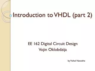
6. VHDL 을 이용한 순차논리회로 설계. 1. 순차논리회로. 순차논리회로 (sequential logic circuit) 출력이 현재의 입력과 과거의 입력에 의해서 결정됨 기억소자가 필요 1.1 래치 (latch) 래치 : 논리게이트로 구성된 기본적인 플립플롭 (flip-flop) 궤환 경로를 가짐 S-R latch (a) 기호 (b) 회로 (c) 진리표

E N D
1. 순차논리회로 • 순차논리회로 (sequentiallogic circuit) • 출력이현재의 입력과 과거의 입력에 의해서 결정됨 • 기억소자가 필요 1.1 래치(latch) • 래치:논리게이트로 구성된 기본적인 플립플롭 (flip-flop) • 궤환경로를 가짐 • S-R latch (a) 기호 (b) 회로 (c) 진리표 그림 6.1 피드백 경로를 갖는 SR 래치.
SR 래치의 동작 1. S=R=0 일 때 다음 상태의 출력은 전 상태 (Q의 현재 값)를 유지 2. S=0, R=1 일때 현재 상태의 값을 0으로 리셋(reset) 한다. 3. S=1, R=0 일 때 현재 상태의 값을 1로 셋 (set) 한다. 4. S=R=1 일 때 Q와 Q’가 0이 되어 래치의 기본 자정에 위해, 사용 금지된 입력
래치의 설계 (a) 진리표 (b) 기호 그림 6.2 enable 입력을 갖는 SR 래치의 진리표와 기호.
VHDL을 위한 엔티티 선언과 내부회로 설계 (a) 엔티티 (b) 회로도 그림 6.3 래치 회로의 엔티티 정의와 내부 회로도.
VHDL을 통한 회로의 기술 • IF문을 이용한 기술 • enable을 갖는 SR래치의 설계 (예제 1) library ieee; use ieee.std_logic_1164.all; entity enSR_latch is port( S,R,E:instd_logic; q, nq : buffer std_logic); end enSR_latch; architecture arc of enSR_latch is begin process(S,R) begin if E = '1' then if S='1' then Q <= '1'; NQ <= not Q; elsif R='1' then Q <= '0'; NQ <= not Q; else Q <= not (NQ); end if; end if; end process; end arc;
프로시저를 이용한 기술 • enable을 갖는 SR 래치의설계 (예제 2) library ieee; use ieee.std_logic_1164.all; entity enSR_latch2 is port( S,R,E:instd_logic; q, nq : buffer std_logic); end enSR_latch2; architecture arc of enSR_latch2 is procedure SR_latch(in_S, in_R, in_E: in std_logic; variable out_q, out_nq: inoutstd_logic) is begin out_q := ((in_enandin_s) nandout_nq); out_nq := ((in_enandin_r) nandout_q); end SR_latch; begin process(E,S,R) variable var_q, var_nq:std_logic; begin var_q := q; var_nq := nq; LR1:SR_latch (S,R,E,var_q,var_nq); q <= var_q; nq <=var_nq; end process; end arc;
1.2 플립플롭 (flip-flop) • 플립플롭:클럭 신호의 상승 또는 하강 에지 (edge)에 동기되어 출력이 변하는 회로 • 플립플롭의클럭 설계 • 상승 클럭(risingedge of clock) if rising_edge (clk) then ~ end if; --package에 정의된 것을 이용 ifclk’event and clk=‘1’ then ~ end if --신호의속성을 이용 • 하강 클럭(fallingedge of clock) if falling_edge (clk) then ~ end if; --package에 정의된 것을 이용 ifclk’event and clk=‘0’ then ~ end if --신호의속성을 이용
D 플립플롭의 설계 (a) 기호 (b) 진리표 그림 6.6 D 플립플롭의기호와 진리표. 그림 6.7 D-FF의 엔티티 정의.
VHDL을 통한 회로의 기술 • IF를 이용한 기술 • D 플립플롭의설계 (예제 1) library ieee; use ieee.std_logic_1164.all; entity D_FF is port( D, clk:instd_logic; Q, NQ: out std_logic); end D_FF; architecture arc of D_FF is begin process(clk) begin if rising_edge(clk) then Q <= D; NQ <= not D; end if; end process; end arc;
D 플립플롭의설계 (예제 2) - 하강 에지 library ieee; use ieee.std_logic_1164.all; entity D_FF is port( D, clk:instd_logic; Q, NQ: out std_logic); end D_FF; architecture arc of D_FF is begin process(clk) begin if rising_edge(clk) then Q <= D; NQ <= not D; end if; end process; end arc;
wait~ until을 이용한 기술 • D 플립플롭설계 (예제 3) library ieee; use ieee.std_logic_1164.all; entity D_FF is port( D, clk:instd_logic; Q, NQ: out std_logic); end D_FF; architecture arc of D_FF is begin process begin wait until rising_edge (clk); Q <= D; NQ <= not D; end process; end arc;
JK 플립플롭의설계 • RS 플립플롭의금지된 입력을 개선한 것 • J=R, K=S 역할, 단 R=S=1 인 경우 금지된 입력인데, J=K=1이면 출력은 이전 상태의 반전 (toggle) (a) 기호 (b) 진리표 그림 6.10 JK 플립플롭의기호와 진리표.
VHDL을 통한 회로의 기술 • IF문을 이용한 기술. • JK 플립플롭의 설계 (예제 1) library ieee; use ieee.std_logic_1164.all; entity JK_FF is port( J,K, clk: in std_logic; Q, NQ:bufferstd_logic); end JK_FF; architecture arc of JK_FF is begin process(J,K,clk) begin if (clk'event and clk='1') then if( J='1' and K='0' )then Q <= '1‘; NQ <= '0'; elsif (J='0' and K='1') then Q <= '0‘; NQ <= '1'; elsif (J= '1' and K='1') then Q <= not Q; NQ <= not NQ; else --(J='0' and K='0') 인경우 Q <= Q; NQ <= NQ; end if; end if; end process; end arc;
JK 플립플롭의설계 (예제 2)- set과 reset을 갖는 JK F/F library ieee; use ieee.std_logic_1164.all; entity JK_FF is port( J,K, clk: in std_logic; set, reset: in std_logic; Q, NQ:bufferstd_logic); end JK_FF; architecture arc of JK_FF is begin process(set, reset, clk) begin if set='1' then Q <='1‘; NQ <='0'; elsif reset='1' then Q <='0‘; NQ <='1'; elsif (clk'event and clk='1') then if( J='1' and K='0' )then Q <= '1‘; NQ <= '0'; elsif (J='0' and K='1') then Q <= '0‘; NQ <= '1'; elsif (J= '1' and K='1') then Q <= not Q; NQ <= not NQ; else --(J='0' and K='0') Q <= Q; NQ <= NQ; end if; end if; end process; end arc;
T 플립플롭 설계 • T 플립플롭: T 값이 0인 경우- 이전 상태 유지, T값이 1인 경우-이전 상태의 반전 그림 6.14 T 플립플롭의기호와 진리표. 그림 6.14 T 플립플롭의엔티티 정의.
함수를 이용한 기술 • T 플롭프롭의설계 (예제 2) - 혼합형 library ieee; use ieee.std_logic_1164.all; entity T_FF is port( T, clk: in std_logic; Q, NQ: buffer std_logic); end T_FF; architecture arc of T_FF is function change(in_t, in_q: std_logic) return std_logic is variable var_t : std_logic; begin var_t := in_q; if in_t = '1' then var_t := not (in_q); end if; return var_t; end change; begin process(clk) begin if rising_edge (clk) then Q <= change ( T, Q); end if; end process; NQ <= not Q; end arc;
2. 카운터 설계 • 카운터 (counter): 클럭 펄스가 인가될 때마다 미리 정해진 순서에 따라 상태를 반보하는 디지털 회로 • 동기식 카운터, 비동기식 카운터 1.1 동기식 카운터 • 동기식 카운터:회로 구성에 사용된 모든 플립플롭들이 하나의 공통 클럭에 연결되어 동작하는 카운터. • 3bit 2진 업 다운 카운터 설계 그림 6.18 3 bit up/down counter.
VHDL을 위한 엔티티 선언 • reset이 1인 경우: 카운터 멈춤초기 상태 • control이 1인 경우: 카운터 증가 • control이 0인 경우: 카운터 감소 그림 6.19 3 bitup/down counter의 엔티티 정의.
VHDL을 통한 회로 기술 • 3bit up/down 카운터설계 library ieee; use ieee.std_logic_1164.all; use ieee.std_logic_unsigned.all; entity updown_cnt1 is port( reset, clk, ctrl: in std_logic; Q: buffer std_logic_vector (2 downto 0)); end updown_cnt1; architecture arc of updown_cnt1 is begin process (clk) begin if reset = '1' then Q <= "000"; elsif (clk'event and clk='1') then if (ctrl='1') then Q <= Q+1; else Q <= Q-1; end if; end if; end process; end arc;
존슨카운터(johnsoncounter) 설계 그림 6.21 존슨카운터의 기호. 그림 6.22 4bit johnson counter의 엔티티 정의.
VHDL을 통한 회로의 기술 • 4 bitJohnson 카운터설계 library ieee; use ieee.std_logic_1164.all; use ieee.std_logic_unsigned.all; entity johnson_cnt is port( reset, clk: in std_logic; Q: buffer std_logic_vector (3 downto 0)); end johnson_cnt; architecture arc of johnson_cnt is begin process(clk, reset) begin if (clk'event and clk='1') then if (reset = '0' ) then Q <= (others => '0'); else Q(3) <= Q(2); Q(2) <= Q(1); Q(1) <= Q(0); Q(0) <= not Q(3); end if; end if; end process; end arc;
1.2 비동기식 카운터 (asynchronouscounter) • 카운터에사용된 플립플롭들이 서로 다른 클럭을 사용하는 형태로 구성된 카운터 • 4 비트 바이너리 증가형리플카운터(ripplecounter) 그림 6.24(a) 4bit 증가형리플 카운터 회로.
(a) 기호 (b) 진리표 그림 6.24 4 bitbinary 증가형리플 카운터.
VHDL을 위한 엔티티 선언 그림 6.25 4bit binary 증가형리플 카운터의 엔티티 정의.
VHDL을 통한 회로의 기술 • 4 bitbinary 증가형리플 카운터를 위한 T 플립플롭설계 library ieee; use ieee.std_logic_1164.all; entity T_FF is port( T, clk:instd_logic; Q : buffer std_logic); end T_FF; architecture arc of T_FF is begin process(clk, T) begin if clk'event and clk='1' then if T='1' then Q <= not Q; end if; end if; end process; end arc;
4bit binary 증가형리플 카운터 설계 library ieee; use ieee.std_logic_1164.all; entity binary_cnt is port( control, clk: in std_logic; Q3, Q2, Q1, Q0 : buffer std_logic); end binary_cnt; architecture arc of binary_cnt is component T_FF port( T, CLK: in std_logic; Q:buffer std_logic); end component; signal NQ : std_logic_vector (0 to 2); begin U0: T_FF port map(control, clk, Q0); NQ(0) <= not (Q0); U1: T_FF port map(control, NQ(0), Q1); NQ(1) <= not (Q1); U2: T_FF port map(control, NQ(1), Q2); NQ(2) <= not (Q2); U3: T_FF port map(control, NQ(2), Q3); end arc;
그림 6.26 4bit binary 리플카운터에대한 시뮬레이션 결과.
리플 카운터를 이용한 16진 클럭 분배기 설계 그림 6.27 주파수 16 분주 분배기.