Download
1 / 12
120 likes | 133 Vues
Power Converter Systems Graduate Course EE8407. Bin Wu PhD, PEng Professor ELCE Department Ryerson University Contact Info Office: ENG328 Tel: (416) 979-5000 ext: 6484 Email: bwu@ee.ryerson.ca http://www.ee.ryerson.ca/~bwu/. Ryerson Campus. Topic 8

E N D
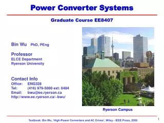
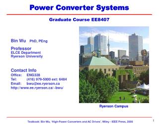
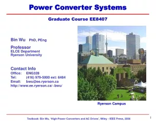
Power Converter Systems Graduate Course EE8407 Bin Wu PhD, PEng Professor ELCE Department Ryerson University Contact Info Office: ENG328 Tel: (416) 979-5000 ext: 6484 Email: bwu@ee.ryerson.ca http://www.ee.ryerson.ca/~bwu/ Ryerson Campus
Topic 8 Other Multilevel Voltage Source Converters Five-Level NPC/H-Bridge Inverter System with dual 18-pulse rectifier LEDAR, Ryerson University
Other Multilevel Voltage Source Converters Lecture Topics • NPC/H-Bridge Inverters • Flying-Capacitor Inverters
NPC/H-Bridge Inverters • Five-Level Topology • Compared with three-level NPC Topology: • Voltage levels increases from three to five • Inverter output voltage and power are doubled • Device count is doubled
NPC/H-Bridge Inverters • IPD Modulation
NPC/H-Bridge Inverters • Waveforms and FFT (Five Level) Inverter Phase Voltage Line-to-line Voltage
NPC/H-Bridge Inverters • Waveforms and FFT (Five Level) Frequency modulation index: mf = 18
Multilevel Flying Capacitor Inverters • Five Level Topology Complementary Switch pairs: S1 and S’1; S2 and S’2; S3 and S’3; S4 and S’4;
Multilevel Flying Capacitor Inverters • Switching State (five-level)
Multilevel Flying Capacitor Inverters • Phase-Shifted PWM • fsw (device) = 60(mf ) = 720Hz • fsw (inverter) = 60(4mf ) = 2880Hz
Multilevel Flying Capacitor Inverters • Summary Features - Low harmonic distortion with low dv/dt - Modular design Drawbacks - Large number of dc capacitors - Complex pre-charging circuits - Difficulties in dc cap voltage balancing control