Download
1 / 80
810 likes | 824 Vues
Explore sequential circuit analysis and design in digital design, covering D, JK, and T flip-flops. Learn VHDL representations with examples and characteristic tables to understand circuit behavior. Dive into state tables and diagrams for Mealy and Moore models. Compare Moore and Mealy machines and their applications. Discover how to analyze circuits using flip-flops and state tables, studying the transition between current and next states.

E N D
ENG2410Digital Design: Week #7“Sequential Circuits: Part B” S. Areibi School of Engineering University of Guelph
Topics • Sequential Circuit Analysis • Sequential Circuit Design • Designing with D Flip-Flops • Designing with JK Flip-Flops • Designing with T Flip-Flops • VHDL Representations • Examples
Resources Chapter #6, Mano Sections • 6.4 Sequential Circuit Analysis • 6.5 Sequential Circuit Design • 6.7 VHDL Representation of Sequential circuits
Analysis of Sequential Circuits • Earlier we learned how to analyze combinational circuits • We will extend analysis to synchronous sequential • We’ll use • State tables and • State diagrams
Analysis vs. Design • The analysis of sequential circuits starts from a circuit diagramand culminates in a state table or state diagram. • The design of a sequential circuit starts from a set of specifications and we should obtain the state diagram and finally the logic diagram.
Characteristic Tables Characteristic tables will be used to analyze the behavior of sequential circuits.
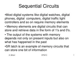
Analysis of Sequential Circuits • The behavior of a sequential circuit is determined from: • Inputs, • Outputs, • Present state of the circuit. • The analysis of a sequential circuit consists of: • Deriving the Input Equations to the Flip Flops. • Obtaining a STATE TABLE • Obtaining a suitable description that demonstrates the time sequence of inputs, outputs and states (STATE DIAGRAM).
Step #1: Derive Input Equations Can describe inputs to FF with logic equations X.B Y’.C
Input Equations The input equations • Imply the type of flip-flop from the letter symbols, • Fully specify the combinational circuit that drives the flip-flops.
Time is Implied • Note that previous circuits used the • Present state (A, B, ..) to determine next state • State and inputs to determine output • Synchronous circuit • When are transitions?
Step #2: State Table • Similar to truth table with state added • A sequential circuit with `m’ FFs and `n’ inputs needs 2m+n rows in state table. • Next State and output are determined using? (input equations) Left Hand Side Right Hand Side
Input Step#3: State Diagram “Mealy Model” Output Input Output An alternative representation to State Table 0/0 00 01 1/0 Input/Output
Sequential Circuit Types Moore model– outputs depend on states only. Mealy model – outputs depend on inputs&states
State Diagram: Moore xy,xy Inputs 00,11 0/0 1/1 00,11 01,10 State/Output Inputs State/Output
Moore vs. Mealy Machine • Moore Machine: • Easy to understand and easy to code. • Might requires more states (thus more hardware). • Mealy Machine: • More complex since outputs are a function of both the state and input. • Requires less states in most cases, therefore less components. • Choice of a model depends on the application and personal preference. • You can transform a Mealy Machine to a Moore Machine and vice versa.
State Table vs. Diagram • Provides same information • Table is perhaps easier to fill in from description • Diagram is easier for understanding and writing code • Analysis for sequential circuits that employs D flip flops is easy. Why? • Because the next state values are obtained directly from the input equations.
Analysis with JK Flip Flops For circuits with other types of flip flops such as JK, the next state values are obtained by following the two step procedure: • Obtain the binary values of each flip-flop input equation in terms of the present state and input variables. • Use the corresponding flip-flop characteristictable to determine the next state.
Analysis with JK Flip Flops First, Obtain the input equations for each flip flop • JA = B • JB = x’ • KA = Bx’ • KB = A’x + Ax’ = A x Next: Build the state table. How many entries?
JK Analysis: State Table • Use the Input equations to determine the FF inputs. • Use the FF inputs and Table to determine the next state. Flip Flop Inputs JK Characteristic Table • JA = B • KA = Bx’ • JB = x’ • KB = A’x + Ax’ = A x
JK Analysis: State Table Flip Flop Inputs • JA = B • JB = x’ • KA = Bx’ • KB = A’x + Ax’ = A x
JK Analysis: State Diagram 1 1 0 00 11 0 0 0 01 10 1 1
Analysis vs. Design • The analysis of sequential circuits starts from a circuit diagram and culminates in a state table or state diagram. • The design of a sequential circuit starts from a set of specifications and we should obtain the state diagram and finally the logic diagram.
Design Procedure • Design starts from a specification and results in a logic diagram or a list of Boolean functions. • The steps to be followed are: • Derive a state diagram • Assign binary values to the states • Choose the type of flip flops to be used • Obtain the binary coded state table • Use Excitation Tables to derive state table • Derive the simplified flip flop input equations and output equations • Draw the logic diagram
Sequential Circuit Design • Remember that a synchronous sequential circuit is made up of flip flops and combinational gates. • Part of the design is to choose the flip-flop type and combinational circuit structure which, together with the flip-flops produce a circuit that fulfills the stated specification. • How many FLIP FLOPS? • The number of flip-flops is determined from the number of states in the circuit • n flip-flops can represent up to 2n binary states. • Examples: • 2 states requires a single Flip Flop • 4 states requires two flip flops • 8 states requires three flip flops • 7 states requires again three flip flops …
Designing with D Flip-Flops • Four States? • 2 flipflops • Design a clocked sequential circuit that operates according to the state diagram. • Use D Flip Flops • Inputs? • Outputs?
Synthesizing Using D Flip Flops • The next step is to create a state table and then select two D flip flops to represent the four states, labeling their outputs as A and B. • There is one input, x, and one output, y, representing the input sequence and the output value respectively. • Remember that the Excitation Table (characteristic equation) of the D flip flop is • Q(t + 1) = DQ • This means that the next-state values in the state table specify the D input condition for the flip flop.
Designing with D Flip-Flops Determine the logic that drives the flip flop DA ? DA DB ? X DB Y ?
Designing with D Flip-Flops Input equations can be obtained directly from the table using minterms: • A(t + 1) = DA(A, B, x) = ∑m(2,4,5,6) • B(t + 1) = DB(A, B, x) = ∑m(1,3,5,6) • Y = ∑m(1,5)
Designing with D Flip-Flops However, we have to minimize the expression in a similar way used for combinational logic design!
Designing with D Flip-Flops DA = AB’ + BX’ DB= A’X + B’X+ ABX’ Y = B’X
A Sequence Detector Design a circuit that detects a sequence of three ones. Use Moore Machine. • Create the state diagram 0 0 1 00/0 01/0 Input Circuit Detects `111’ at input Output 0 1 0 000011101 11/1 10/0 1 1
A Sequence Detector Design a circuit that detects a sequence of three ones. Use Moore Machine. • Create the state diagram Input Circuit Detects `111’ at input Output Moore Machine
Synthesizing Using D Flip Flops • The next step is to create a state table and then select two D flip flops to represent the four states, labeling their outputs as A and B. • There is one input, x, and one output, y, representing the input sequence and the output value respectively. • The output y is `1’ only when we detect the input sequence of `111’
State Table for Sequence Detector Input equations can be obtained directly from the table using minterms: • A(t + 1) = DA(A, B, x) = ∑m(3, 5, 7) • B(t + 1) = DB(A, B, x) = ∑m(1, 5, 7) • y(A, B, x) = ∑m(6, 7)
Boolean Minimization K-Maps can be used to minimize the input equations, resulting in • DA = Ax + Bx • DB = Ax + B’x • Y = AB
Sequential Circuits with different Flip Flops (JK, T) The design of sequential circuits other than D type flip flops is complicatedby the fact that input equations must be derived indirectly from the state table. • It is necessary to derive a functional relationship between the state table and the input equations.
Excitation Table During the design, we usually know the transition from present to next state but we need to find the flip flop input conditions that will cause the required transition. • We need a table that lists the required inputs for a given change of state, called an excitation table.