Download
1 / 16
160 likes | 298 Vues
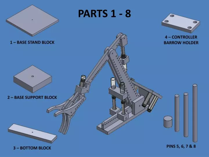
PARTS 1 - 8. 4 – CONTROLLER BARROW HOLDER. 1 – BASE STAND BLOCK. 2 – BASE SUPPORT BLOCK. PINS 5, 6, 7 & 8. 3 – BOTTOM BLOCK. 1 – BASE STAND BLOCK. 2. Extrude Boss/Base .75. 1. Sketch on Top plane. 5. Extruded Cut .50. 4. View Normal To Circle .25. 3. New Sketch on Surface

E N D
PARTS 1 - 8 4 – CONTROLLER BARROW HOLDER 1 – BASE STAND BLOCK 2 – BASE SUPPORT BLOCK PINS 5, 6, 7 & 8 3 – BOTTOM BLOCK
2. Extrude Boss/Base .75 1. Sketch on Top plane 5. Extruded Cut .50 4. View Normal To Circle .25 3. New Sketch on Surface Point to the Top Left-Click your mouse Click Sketch button Save as 1 – BASE STAND BLOCK Put into Titlebox (see next slide)
2. Extrude Boss/Base .75 1. Sketch on Top plane 3. New Sketch on Surface Point to the Top Left-Click your mouse Click Sketch button 5. Extruded Cut Through All 4. View Normal To Circle .25 Save as 2 – BASE SUPPORT BLOCK Put into Titlebox (see next slide)
1. Sketch on Top plane 2. Extrude Boss/Base .75 3. New Sketch on Surface Point to the Top Left-Click your mouse Click Sketch button 5. Extruded Cut Through All 4. View Normal To Circle .25 Save as 3 – BOTTOM BLOCK Put into Titlebox (see next slide)
1. Sketch on Top plane 2. Extrude Boss/Base .75 5. Extruded Cut Through All 3. New Sketch on Surface Point to the Top Left-Click your mouse Click Sketch button 4. View Normal To Four Circles .875 Save as 4 – CONTROLLER BARROW HOLDER Put into Titlebox (see next slide)
Save as 5 – BASE PIN 1. Sketch on Top plane 2. Extrude Boss/Base .50 NOTE: DRAW EACH PIN AS A SEPARATE PART! Make 3 more pins All Sketch on Top plane All ¼” Circles Lengths (Extrude Boss/Base) will be different Save each one separately 6 - PIN Extrude 2 ½” 8 - PIN Extrude 4” 7 - PIN Extrude 3”