Download
1 / 51
510 likes | 705 Vues
Speaker: Daw -Ming Lee Advisor: Chun- Yao Wang 2009.11.12. Appearance-Based Equivalence Checking. Outline . Introduction Proposed approach. Equivalence checking. Given two circuits, golden circuit and revised circuit . Identify whether they are equivalent or not.

E N D
Speaker: Daw-Ming Lee Advisor: Chun-Yao Wang 2009.11.12 Appearance-Based Equivalence Checking
Outline • Introduction • Proposed approach
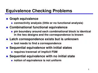
Equivalence checking • Given two circuits, golden circuit and revised circuit. • Identify whether they are equivalent or not.
Traditional approaches • Build BDDs • Drawback • Exponential growth of required memory and runtime
Our ideas • Do not build BDDs. • According to their appearances, transforming one circuit(revised circuit) to a new circuit which is similar to another circuit(golden circuit).
Outline • Introduction • Proposed approach
Multiple-outputs circuit • We see one multiple-outputs circuit as several independentsingle-output circuits, and examine the equivalence of each pair of single output circuits
How to make two circuits identical? • We compare the two circuits, and do some actionsto make them as similar as possible.
Action type • Remove a wire • Add a wire/gate • Gate replacement a a b a a b a a b b
Action classification • Redundant action • may not change the functionality. • Irredundant action (error) • may change the functionality. • needs to add some rectified circuitsto keep the original functionality.
Error model • Design error model proposed by Abadir gate replacement remove a wire add a wire remove a wire + add a wire add wires add a wire remove a wire + add a wire
Fault model • s-a-1 fault • the faulty gate has an MA 0/1 in good/faulty values • s-a-0 fault • the faulty gate has an MA 1/0 in good/faulty values
Error and fault • An error was occurred by one fault or multiple faults. • If we can rectify all the fault(s) causing the error, we can eliminate the error.
Mandatory Assignments (MAs) • The mandatory assignments (MAs) are the unique value assignments required for a test to exist. • We derived a set of MAs for a target fault.
Forced MA • An MA that causes the target fault untestable while violating it.
Essential fanin cone • When propagating a target fault, the side input cone of gb is essential fanin cone if gagood(SMA) is non-controlling value of gb. gb 0/1 gx 1/0 ga non-essential essential
Rectification of a fault • We add a network to rectify the fault. • Where to rectify the fault? • How to derive the rectified circuit for the fault?
Where to rectify the fault? (1/2) • The added network should satisfy the following two conditions. • The added network can make the target fault untestable. • The added network is redundant for original circuit.
Where to rectify the fault? (2/2) • Transitive fanout cone • Non-essential Forced MA
Transitive Fanout Cone (TFC) • The fault may pass to any POs through the transitive fanout cone of the fault. • We can add rectified circuit(s) at TFC to block all the fault effects that possibly arrive any POs. • The added network(s) at TFC can make the target fault untestable. • We will prove the added network(s) at TFC are redundant for the original circuit later.
Transitive fanout cone a g1 g3 b g5 g2 c g4
Transitive fanout cone a g1 g3 b g5 g2 c g4
Non-essential Forced MA • The forced MA is also in non-essential fanin cone. • We can violate the forced MA to make the target fault untestable. • Add at non-essential fanin cone can ensure the added network is redundant. 0/1 ga gb non-essential
Non-essential Forced MA Forced MA: c = 1 g3 = 0 e = 1 0 0/1 a g4 g1 g3 g5 g2 0/1 b 0 1 c 0/1 0/1 a 0 1 d e
Rectification of a fault • We add a network to rectify the fault. • Where to rectify the fault? • How to derive the rectified circuit for the fault?
How to derive the rectified circuit for the fault? • Transitive fanout cone • For the case without branch. • For the case with branch. • Non-reconverge gate • Reconverge gate • Non-essential forced MA
For the case without branch • Let M denote a set of MAs of a target fault obtained by logic implication without recursive learning. • We use E to denote a set of MAs that is a subset of M and in the essential fanin cone . • Source MAs (SMAs), S, are the MAs that satisfy the following conditions: • Implication(S) = E • Let s denote one element in S. The transitive fanin cone of s contains no other elements in S.
For the case without branch • We can propagate a fault to the destination with a specific fault, 0/1 or 1/0. • The AND(SMAs) can represent a network that contains all minterms that change from true value to faulty value with the specific fault.
Rectified circuit at a transitive fanout cone • 0/1 fault • 1/0 fault … SMAs 1/0 gn gd Fault:0/1 1 SMA … 1/0 gn gd Fault:1/0 0
For the case without branch 0 0/1 a g1 g4 g3 g5 g2 0/1 b 0 1 c 0/1 0/1 0 gn a 0 1 ab d e
How to derive the rectified circuit for the fault? • Transitive fanout cone • For the case without branch. • For the case with branch. • Non-reconverge gate • Reconverge gate • Non-essential forced MA
For the case with branch • For each path, we can obtain a set of unique assignments. • The rectified network is • AND(SMA) AND(SPA) • Source Path Assignment
Rectified circuit at a non-reconverge gate 0/1 abc 0/1 a g1 gn g3 1/0 b g5 1/0 1 1 0 g2 0 c g4
Rectified circuit at a non-reconverge gate 0/1 0/1 a g1 0 0/1 g3 b g5 1 g2 0/1 c g4 gn abc 1
Rectified circuit at a reconverge gate • gd EAN + ERN • EAN = AND(SMA) gdg(SMA) • ERN = AND(SMA) gdg(SMA)
Rectified circuit at a reconverge gate 0/1 abc 0 a g1 c gn g3 c b g5 1 gn abc c g2 0 c g4
How to derive the rectified circuit for the fault? • Transitive fanout cone • For the case without branch. • For the case with branch. • Non-reconverge gate • Reconverge gate • Non-essential forced MA
Rectified circuit at a non-essential forced MA • Forced MA : 1 • Forced MA : 0 1 SMAs … gn gd 0 Forced MA:1 1 SMA … gn gd 1 Forced MA:0
Non-essential Forced MA 0 0/1 a g4 g1 g3 g5 g2 0/1 b 0 1 c 0/1 0/1 a 0 1 d e gn ab
Rectified circuit of three errors(1/3) • IRredundant removal(IRRA) • only causes one fault • IRredundant addition • Gate replacement
Rectified circuit of three errors(2/3) • IRredundant removal(IRRA) • only causes one fault • IRredundant addition • may cause a fault or multiple faults • Gate replacement
IRredundant addition (1/6) 1/0 a b a ab
IRredundant addition (2/6) 1/0 a b a ab
IRredundant addition (3/6) a b ab a ab ab
IRredundant addition (5/6) a b ab a
IRredundant addition (6/6) a b ab a
Rectified circuit of three errors(3/3) • IRredundant removal(IRRA) • only causes one fault • IRredundant addition • may cause a fault or multiple faults • Gate replacement • may cause double faults
Gate replacement a a b ab b ab
Gate replacement a a b ab b ab