Download
1 / 23
290 likes | 1.3k Vues
LECTURE 4 DIODE LED ZENER DIODE DIODE LOGIC. Diode Conduction & Current Flow. Diodes allow current to flow in one direction only The diode conducts when the anode is biased positively with respect to the cathode Semiconductor diodes always include special marks on the packages

E N D
Diode Conduction & Current Flow • Diodes allow current to flow in one direction only • The diode conducts when the anode is biased positively with respect to the cathode • Semiconductor diodes always include special marks on the packages • The circuit schematic symbol forms an arrow that points in the direction of current flow when the anode is biased positively with respect to the cathode, the “forward conduction region”.
Current-Voltage Characteristics • The current voltage characteristic of a typical semiconductor diode • Note that the reverse saturation current is exaggerated for clarity, and the reverse breakdown voltage Vbr is usually much large than the forward turn-on Vt.
Current-Voltage Characteristics • Above the forward threshold voltage Vtthe current increases exponentially. Under reverse bias only a tiny reverse saturation current flows until breakdown is encountered at which point the current increases rapidly • There are basically three parameters that describe the operation: Vt, Vbr, and the maximum current that the device can sustain during operation
Current-Voltage Characteristics • The impact of these model parameters varies with application • In the AM “crystal” radio, the signal levels are very small a diode with a small turn-on voltage is desirable • In a power-supply application, devices that can sustain large forward currents and reverse voltages are often preferred
Current-Voltage Characteristics • The turn-on voltage is largely governed by the choice of semiconductor material and the device design • Silicon-based PN junction diodes have threshold voltages (Vt)of 0.6-0.8V, typically 0.7V • Germanium PN junction diode have threshold voltage of (Vt) 0.3V. • The current-handling capacity is often limited by thermal considerations (the device can be destroyed with too much current and/or poor heat sinking and) but this can be manipulated by geometrical factors such as the device cross section, so devices of various sizes with a wide range of current-handling capacities are available
Diode Packages Example part number of a diode: 1N4148, 1N400x Any part number beginning with “1N” is always a diode. However, not all diode part numbers begin with “1N”!
Diode Packages • The 1N4148 is usually listed under the heading of “small-signal diodes” or “switching” diodes. • The 1N400x is usually listed under the heading of “rectifier” diodes • What is the difference between the two? • voltage and current handling capability • the 1N4148 can handle currents of up to 300 mA and peak reverse voltages of 75V • the1N400x can handle up to 1A and voltages ranging from 60V (1N4001) to 1200V (1N4007).
Diode Packages • So the 4148 tends to be used in applications where the currents are small, for example in an audio amplifier circuit • The 400x is designed for abuse and is a good choice in power-supply applications • There are lots of other diodes available on the market; this discussion is just intended to make you aware that diode selection involves a number of considerations beyond threshold voltage
Light-Emitting Diodes and Displays • Light emitting diodes (LEDs) are diodes made with direct bandgap semiconductors (GaAs, GaN, etc.) • LEDs are designed to generate light when enough current passes through the device • LEDs are functional similar to any diode, but they typically have a much larger threshold voltage • ~2V for red and green LEDs • ~4V for blue and white LEDs • The packaging is also necessarily different, with a variety of sizes and lens configurations for various display requirements
Light-Emitting Diodes and Displays • The cathode leg of the LED is the shorter of the two • LEDs are used in lots of applications and come in a variety of packages • LED symbols are the same as a regular diode with little arrows to suggest light
Light-Emitting Diodes and Displays • LED displays include multiple LEDs arranged in a fixed pattern with shaped lenses, the most familiar pattern being the 7-segment displays for showing numbers (digits 0-9)
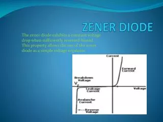
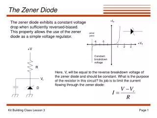
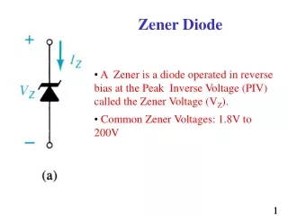
Zener Diode • A Zener Diode is a special kind of diode which permits current to flow in the forward direction as normal • The current also flows in the reverse direction when the voltage is above a certain value - the breakdown voltageknown as the Zener voltage
Zener Diode • Typical Zener voltage, Vz, is 2.4V • The voltage drop across the Zener diode is equal to the Zener voltage of that diode no matter how high the reverse bias voltage is above the Zener voltage.
Zener Diode • Zener diodes are typically used to regulate the voltage in electric circuits • Since the voltage dropped across a Zener Diode is a known and fixed value • Using a resistor to ensure that the current passing through the Zener diode is at least 5mA (0.005 Amps), the circuit designer knows that the voltage drop across the diode is exactly equal to the Zener voltage of the diode
DIODE LOGIC – AND GATE • The AND gate performs logical multiplication, commonly known as AND function. The AND gate has two or more inputs and single output. The output of AND gate is HIGH only when all its inputs are HIGH (i.e. even if one input is LOW, Output will be LOW Truth Table Symbol
DIODE LOGIC – AND GATE • If X = 0 and Y = 0, then both diodes D1 and D2 are forward biased and thus both diodes conduct and pull F low • If X = 0 and Y = 1, D2 is reverse biased, thus does not conduct. But D1 is forward biased, thus conducts and thus pulls F low • If X = 1 and Y = 0, D1 is reverse biased, thus does not conduct. But D2 is forward biased, thus conducts and thus pulls F low • If X = 1 and Y = 1, then both diodes D1 and D2 are reverse biased and thus both the diodes are in cut-off and thus there is no drop in voltage at F. Thus F is HIGH
DIODE LOGIC – AND GATE • In the figure below, X and Y are two switches which have been connected in series (or just cascaded) with the load LED and source battery. When both switches are closed, current flows to LED Switch Representation of AND Gate
DIODE LOGIC – OR GATE • The OR gate performs logical addition, commonly known as OR function. The OR gate has two or more inputs and single output. The output of OR gate is HIGH only when any one of its inputs are HIGH (i.e. even if one input is HIGH, Output will be HIGH) • If X and Y are two inputs, then output F can be represented mathematically as F = X+Y. Here plus sign (+) denotes the OR operation. Truth table and symbol of the OR gate is shown in the figure below Truth Table Symbol
DIODE LOGIC – OR GATE • If X = 0 and Y = 0, then both diodes D1 and D2 are reverse biased and thus both the diodes are in cut-off and thus F is low • If X = 0 and Y = 1, D1 is reverse biased, thus does not conduct. But D2 is forward biased, thus conducts and thus pulling F to HIGH • If X = 1 and Y = 0, D2 is reverse biased, thus does not conduct. But D1 is forward biased, thus conducts and thus pulling F to HIGH • If X = 1 and Y = 1, then both diodes D1 and D2 are forward biased and thus both the diodes conduct and thus F is HIGH
DIODE LOGIC – OR GATE • In the figure, X and Y are two switches which have been connected in parallel, and this is connected in series with the load LED and source battery. When both switches are open, current does not flow to LED, but when any switch is closed then current flows Switch Representation of OR Gate Source: http://www.asic-world.com/digital/gates1.html
AC to DC Power Supply • http://www.youtube.com/watch?v=cyhzpFqXwdA