Download
1 / 27
270 likes | 387 Vues
2 nd Order Circuits. Boundary Conditions. Objective of Lecture. Demonstrate how to determine the boundary conditions on the voltages and currents in a 2 nd order circuit. These boundary conditions will be used when calculating the transient response of the circuit. 2 nd Order Circuits.

E N D
2nd Order Circuits Boundary Conditions
Objective of Lecture • Demonstrate how to determine the boundary conditions on the voltages and currents in a 2nd order circuit. • These boundary conditions will be used when calculating the transient response of the circuit.
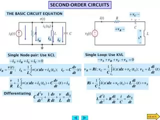
2nd Order Circuits • A second order differential equation is required to solve for the voltage across or the current flowing through a component. • The circuit will contain at least one resistor and the equivalent of two energy storage elements • 2 capacitors, 2 inductors, or a capacitor and an inductor
Boundary Conditions • Steady state • For step response functions u(t- to) for all times between t = +/- ∞ except for some time period after t = to • Capacitors are opens • Inductors are short circuits • During the transition at the step t = to • Voltage across a capacitor is continuous • vC(to +) = vC (to -) • Current through an inductor is continuous • iL(to +) = iL(to -)
Initial Condition • Redraw the circuit at t < to • Determine the value of all voltage and current sources at t< to • Make the appropriate substitutions for the energy storage devices. • Substitute an open circuit (∞W resistor) for all capacitors. • Note: IC(t < to ) = 0A. • Substitute an short circuit (0W resistor) for all inductors. • Note: VL(t < to ) = 0V. • Calculate VC(t < to ) and IL(t < to ).
Final Condition • Redraw the circuit at t =∞ s • Determine the value of all voltage and current sources at t =∞ s • Make the appropriate substitutions for the energy storage devices. • Substitute an open circuit (∞W resistor) for all capacitors. • Note: iC(t =∞ s) = 0A. • Substitute an short circuit (0W resistor) for all inductors. • Note: vL(t =∞ s) = 0V. • Calculate vC(t =∞ s) and iL(t =∞ s).
Example #1 (con’t) • Initial Condition: The circuit is:
Example #1 (con’t) iL (-∞) = iL (to-) = 0AvL (-∞) = vL (to-) = 0V iC (-∞) = iC (to-) = 0A vC (-∞) = vC (to-) = [R2/(R1+R2)]V ∞W
Example #1 (con’t) • Final Condition: The switch opens, • which removes V1 and R1 from the circuit.
Example #1 (con’t) • The energy stored in the inductor and capacitor will be dissipated through R2 and R3 as t increased from t= to.
Example 1 (con’t) • At time t = ∞s, the energy stored in the inductor and in the capacitor will be completely released to the circuit. ∞W
Example #1 (con’t) iL (∞s) = 0AvL (∞s) = 0V iC (∞s) = 0AvC (∞s) = 0V ∞W
Example #1 (con’t) For to < t << ∞s iL (t) ≠ 0vL t) ≠ 0 iC (t) ≠ 0 vC (t) ≠ 0
Electronic Response • Draw the circuits when t < to and t = ∞s for the following circuit:
Example #2 (con’t) iL (-∞s) = 0.3mAvL (-∞s) = 0V iC (-∞s) = 0A vC (-∞s) = 3.5V
Example #2 (con’t) iL (∞s) = 0AvL (∞s) = 0V iC (∞s) = 0A vC (∞s) = 5V
Example #3 (con’t) iL1 (-∞s) = -1mAvL1 (-∞s) = 0V iL2 (-∞s) = 1mA vL1 (-∞s) = 0V
Example #3 (con’t) iL1 (∞s) = -1mAvL1 (∞s) = 0V iL2 (∞s) = 1.4mA vL2(∞s) = 0V
Example #4 (con’t) iL1 (-∞s) =- 1 mA vL1 (-∞s) = 0V iC1 (-∞s) = viC2 (-∞s) = 0A vC1 (-∞s) = vC2 (-∞s) = 4V
Example # 4 (con’t) iL1 (∞s) = 0mAvL1 (∞s) = 0V vC1 (∞s) = vC2 (∞s) = 1ViC1 (∞s) = iC2 (∞s) = 0A
Summary • Calculation of the initial and final conditions for 2nd order circuits requires: • Knowledge of the magnitude of the voltage and/or current sources in the circuit before and after a step function transition. • In steady state (t < to and t = ∞s), replace energy storage devices. • Capacitors are opens circuits => iC = oA • Inductors are short circuits => vL = oA • Calculate the voltage across the capacitor and the current through the inductor. • During the transition at the step t = to • Voltage across a capacitor is continuous • vC(to +) = vC(to -) • Current through an inductor is continuous • iL(to +) = iL(to -)