Download
1 / 14
170 likes | 383 Vues
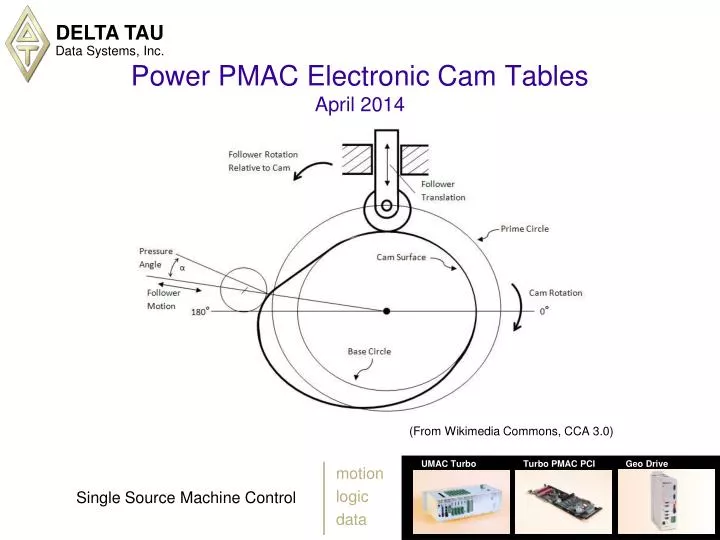
Power PMAC Electronic Cam Tables April 2014. (From Wikimedia Commons, CCA 3.0). Power PMAC Cam Table Functionality. Table-based commanded motion as function of another position Up to 256 total cam tables stored simultaneously Table size limited only by total memory

E N D
Power PMAC Electronic Cam TablesApril 2014 (From Wikimedia Commons, CCA 3.0)
Power PMAC Cam Table Functionality • Table-based commanded motion as function of another position • Up to 256 total cam tables stored simultaneously • Table size limited only by total memory • Three separate table outputs as a function of master position • Commanded position/position-offset for target motor • Torque offset for slaved motor • General-purpose output word (multiple discrete outputs or analog command) • Outputs computed every servo cycle • 3rd-order interpolation between table points for position and torque • Automatic indefinite rollover of table in both directions • Position and torque values are floating-point, scalable units • Easy to offset both source and target position references • Easy to switch from one table to another
Cam Table Data Structure Overview • Data structure elements about source motor • CamTable[m].Source // Source motor number • CamTable[m].Nx // Number of data zones in table • CamTable[m].X0 // Starting (minimum) position of source • CamTable[m].Dx // Span of source position • Data structure elements about target motor • CamTable[m].Target // Target motor number • CamTable[m].PosSf // Position output scale factor • CamTable[m].DacSf // Torque-offset output scale factor • Data structure elements for table entries • CamTable[m].PosData[i] // Individual position output value • CamTable[m].DacData[i] // Individual torque-offset output value • CamTable[m].OutData[i] // Individual general-purpose output value
Cam Table Source Motor • “Source” position for cam table must be from Power PMAC “motor” • Table uses desired position from motor specified by CamTable[m].Source • Source motor (real or virtual) should be in separate coordinate system from target motors (often C.S. 0) • Can be from actual physical motor controlled by Power PMAC • Can be from position sensor for motion not controlled by Power PMAC • Sensor must be used as position feedback for Power PMAC virtual motor • Motor must be activated (to process feedback) but should not be enabled • Sensor position automatically copied into motor desired position register • Can be from desired trajectory of virtual motor • Commonly used for “virtual line shaft” • Jogging this motor can be enough to cause all action of cam table(s)
Returning vs. Non-Returning Cam Tables • “Returning” cam tables have same position at beginning and end • PosData[Nx] must be exactly the same value as PosData[0] • Typically used for (reciprocating) linear action from table • Every cycle of table covers same range • “Non-returning” cam tables have different beginning and end position values • PosData[Nx] has different value from PosData[0] • Typically used for rotary action from table (one revolution per cycle) • Each cycle of table covers different position range • Torque offset and general-purpose output values always “returning”
Establishing Position Lock on Enabling • In general, target motor will not be at table-commanded position when table is enabled • Power PMAC sets CamTable[m].PosOffset to (signed) difference between present and desired values on enabling • Then, each servo cycle, offset is reduced by CamTable[m].SlewPosOffset until difference is eliminated • For non-returning table, choice of which “instance” of table curve to lock onto, controlled by value of CamTable[m].Enable • Enable = 1: Always slew in positive direction • Enable = 2: Always slew in negative direction • Enable = 3: Slew to closest curve
Position Action of Cam Table • Each servo cycle, Power PMAC computes position of source motor within table • Using two PosData points on each side of this position, uses cubic interpolation to compute cam position value • Automatically handles rollover of table, returning or non-returning • This value multiplied by CamTable[m].PosSf (usually 1.0) • Result is written to Motor[x].CompDesPos register for target motor • This desired position compensation value is added to trajectory desired position and master position for target motor (possible to superimpose) • If want compensation value to be reported when querying motor position, set Motor[x].PosReportMode to 1.
Torque Offset Action of Cam Table • Each servo cycle, Power PMAC computes position of source motor within table • If CamTable[m].DacEnable = 1, will compute torque offset based on this position • Using two DacData points on each side of this position, uses cubic interpolation to compute cam torque-offset value • This value multiplied by CamTable[m].DacSf (usually 1.0) • Result is written to Motor[x].CompDac register for target motor • This servo-output compensation value is added to value computed by selected servo algorithm of target motor this servo cycle • Can be used to compensate for known repeatable load torques in cycle • Table values can be adjusted automatically with “iterative learning control” algorithms • Many applications will not use at all – just leave all DacData points at 0.0, and/or DacEnable at 0
General-Purpose Output Action of Cam Table • Each zone of table has user-specified output “word” OutData[i] • 1 to 32 bits can be written to single specified register • Can represent group of discrete digital outputs • Can represent single analog output value • Can represent value for further software action • CamTable[m].pOut specifies address of destination register • e.g. = Acc68E[2].DataReg[4].a • CamTable[m].pOutBuf specifies address of holding register • Used if cannot read back from output destination register • Holding register is modified, then copied to actual output register • CamTable[m].OutBits specifies number of bits to control • Must be consecutive bits in output word • CamTable[m].OutLeftShift specifies shift of table value before writing • Typically set to number of LSB used in output register
Adjusting Cam Table Reference Positions • Adjusting source motor table reference position • CamTable[m].X0 specifies reference position (where PosData[0], DacData[0] are used) • X0 can be changed at any time • Actual reference position used (ActiveX0) changes at rate set by SlewX0. • Can set X0 based on trigger position using Motor[x].CapturePos function • Adjusting target motor table reference position • CamTable[m].PosOffset specifies value to be added to table result • Power PMAC automatically sets PosOffset on enabling table to control lock-in • After lock-in, user can change PosOffset at any time • Actual reference position used (ActivePosOffset) changes as rate set by PosOffsetSlew • Can also adjust effective reference position through trajectory moves (e.g. jogging) or position following (e.g. handwheel adjustment) of target motor
Cam SculptorTM Table Design Tool • Interactive design tool for specifying Power PMAC electronic cam tables • Not required to generate cam tables, but very useful tool in many cases • Supports traditional (e.g. harmonic, cycloidal) and modern (e.g. minimum power) cam sections • Permits viewing of cam position, velocity, acceleration, and/or jerk • Flags discontinuities and user-set magnitude limits in derivatives • Automatically generates cam table points from user-specified sections • Can download generated table directly to Power PMAC
Comparing Cam Tables to External Time Base • Cam table features • Fully reversible: master can go in either direction indefinitely • Motion defined by table, not motion program • Motion of multiple motors must be defined by multiple tables • No point computation or logic during execution of table • Table points must be evenly spaced • Cam tables have torque offsets and direct outputs as standard features • External time base features • Limited reversibility: master must generally move in positive direction • Motion defined by program, not table • Motion of multiple motors can be defined by a single program • Possibility for point computation and logic during program execution • Programmed moves do not need to be evenly spaced • No torque offsets; synchronous assignments for direct outputs