Download

1 / 14
140 likes | 265 Vues
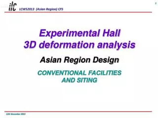
March 22, 2012 920 - 950. Asian Region Civil Design. Outline. Overview of Asian Civil Design Previous Case Study Feature of Beam Tunnel Tunnel Typical Cross Section Beam Tunnel RTML Damping Ring Access Hall and Access Tunnel Central Region Layout. Overview of Asian Civil Design.

E N D
March22,2012 920 - 950 Asian Region Civil Design
Outline • Overview of Asian Civil Design • Previous Case Study • Feature of Beam Tunnel • Tunnel Typical Cross Section • Beam Tunnel • RTML • Damping Ring • Access Hall and Access Tunnel • Central Region Layout
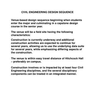
Overview of Asian Civil Design • Beam Tunnel • ‘Kamaboko’ shape (by NATM) • Separated by concrete radiation shield wall (t=3.5m) • Access Tunnel • Sloped tunnel • Two access tunnel for central region (for DR and D/H) • Access Hall • Eight access halls for electric facilities, cooling water plant, cryogenic plant, and the others • 5km intervals is maximum because of He supply • Detector Hall • IP point will be explained later
AT AT BT SbT BT SbT AH AH LC LC AT AT AT ST BT BT SbT BT AH AH PM AT BT SbT AH PM KL AT AT BT BT AH AH Case Study (Earlier Conclusion) Case1 Case2 Case3 Case4 Case8 Case5 Case6 Case7 Adopted Having the advantage with considering a comprehensive view point (cost, schedule, convenience..)
Feature of Beam Tunnel • NATM (drill and blasting method) is adopted • Single tunnel with concrete shield wall (t=3.5m) • Two galleries for beam line and service tunnel (klystron) • Help access to klystron side easily and safely during operation and in case of evacuation
Typical tunnel section • Beam Tunnel • Damping ring tunnel (straight part) • Damping Ring Tunnel (arc part) Shape is called Kamaboko • RTML part of Beam Tunnel
Access Hall & Access Tunnel • Access hall consists of individual cavern • Vibration source is installed away from beam line • Cold boxes are near beam line Cold boxes Electric facilities Cooling water plant He compressor
Maintenance Hall Access Tunnel (sloped Tunnel) Section A-A Beam T Detail Maintenance Hall Beam T Beam T E A A G Maintenance Hall G Access Tunnel (sloped tunnel) E Section G-G (Access Tunnel) Beam Tunnel Section E-E (Maintenance Hall)
B He Compressor Cooling water, Plumbing sys Section B-B C Cooling water, Plumbing sys F F Section C-C H H B C Section H-H (Cooling water, Plumbing sys) He Compressor Section F-F (He Compressor)
D Cryogenic Plant Electric Facilities Cryogenic Plant Section D-D I J J I Section I-I (Connection Tunnel) Section J-J (Cryogenic Plant) K K Electric Facilities D Section K-K (Electric Facilities)
Central Region layout Cold Box and Cooling System Cooling System He Compressor Unit • Cooling systemsfor normal conduction area (arc portion) • He compressor unit for detector is installed at center of dumping ring region • Cold box is installed near superconducting area
Detail of junctional region Passage way Service side Service side Beam Line side Passage way Service side • At junction part, service side is connected to opposite side by over-pass passage ways Service side Beam Line side
Summary • Kamaboko shape tunnel with concrete shield wall is adopted for Beam Tunnel and straight part of Damping Ring • Sloped access tunnel is adopted • Access hall consists of individual 4 caverns