Download
1 / 40
400 likes | 406 Vues
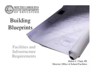
Unit 6.05 and 6.06-Learning about blueprints. Blueprints are reproductions of technical drawings that provide information about how a structure is to be built.

E N D
Unit 6.05 and 6.06-Learning about blueprints • Blueprints are reproductions of technical drawings that provide information about how a structure is to be built. • A document containing all the instructions necessary to manufacture a part. The key sections of a blueprint are the drawing, dimensions, and notes.
Blueprint What is the purpose of a blueprint, and what does it show?
Components of blueprints A. Elevations 1. Interior 2. Exterior B. Floor plans C. Electrical plans D. Climate Control E. Blueprint F. Section Drawing/View G. Rendering H. Detail View I. Plot Plan J. Model
Several sets of blueprints needed One set is filed with the local government. The builder needs blueprints on the job site. One set is given to the client.
Symbols Space is limited on a blueprint, so symbols are used. Symbols are universal.
A set of blueprints includes several types of drawings. • The floor plan- which shows the layout of the rooms as if viewed from above • Other drawings- give information about the foundation, electrical system, and plumbing system
Floor Plan A diagram of a home or other structure that shows the arrangement of rooms
Floor Plan • The most important drawing on a set of house plans is the Floor plan
Basic structures of any building: Foundation Frame
The frame Skeleton of the structure Supports the house Distributes the weight Steel and wood framing- similar in price
Foundation Drawing Plan to help construct the footings, columns, foundation walls, and support beams
The location of the heating, cooling, humidification, dehumidification and air cleaning equipment can be seen on the: Climate control plan
Elevation The finished exterior appearance of a given side of a house The height dimensions of a structure can be found on the Elevation view.
Green Design Philosophy that treats environmental attributes as design goals
Orientation The position of a home on its site and the direction the home faces
Detail View • This view usually shows an enlargement of some construction feature. • When a view is taken from an imaginary cut through a part of a house, such as wall.
Section View Imaginary cut through the wall
Templates • Cut-out patterns of furniture and appliances drawn to scale and used to create a floor plan. • The scale most architects use for a drawing of a home is ¼” = 1’.
Traffic patterns Drawing an architectural plan Shows movement through the house. Major traffic pattern within home is 2- to 4 feet.
Specifications Information in details about interior/exterior materials
Drawings: • Various drawings are used to help clients visualize a design concept. Included are: • 1) Renderings-drawings where realistic details such as textures, shadows, shadings and color are added. • The designer may use pen & ink, water color or CAD software to make the rendering. • Water color is the most realistic appearance to presentation
Rendering (cont.) Felt-tip rendering is very difficult to correct. A Felt Tip pen has a tip that draws the ink from the pen and thru the tip onto the paper. Pencil: soft lead pencil
Drawings, cont’d: 2. Perspectives- provide a more realistic view; shows several surfaces simultaneously. Perspective is the re-creating of an image in relation to the eye of the viewer. One Point Perspective- Shows what is seen when viewer looks at the opposite wall. Two Point Perspective- Shows what is seen when looking at the corner where the two walls meet.
Overlay… A thin sheet of see-through material placed over a basic plan so the plan can be colored, shading without making changes on the basic plan.
The most line types in architectural drawings are: Main Object Lines/ Visible line (outline of building and walls), which define the outline of the structure, or object. They are thick, unbroken lines that show the main outlines of the walls, floors, elevations, details, or sections. ________ Dimension Lines, which provide the lengths of the main object lines. They are very light lines with triangles, resembling arrowheads, on each end. The number that appears in the center break of the dimension line represents the measurement of the specific main object line to which it refers.
The most commonly encountered line types in architectural drawings are: (continued). Extension Lines, Used to extend dimensions from related objects Extend about 3mm beyond of dimension line which are used together with dimension lines, and are the light lines that extend beyond the main object lines. The arrowheads of the dimension lines usually reach and touch the extension lines. __________________________________ A line used to visually connect the ends of a dimension line to the relevant feature on the part. Extension lines are solid and are drawn perpendicular to the dimension line.
The most commonly encountered line types in architectural drawings are: (continued). Hidden Lines, which are light dashes that indicate the outlines of an object normally hidden from view, either under or behind some other part of the structure. The dashes used in this line type are usually of equal length. ----------------------------------------------- HiddenLines: used to represent edges hidden from view. About 3mm the dashes and 1.5 mm apart
The most commonly encountered line types in architectural drawings are: (continued). Center Lines, which are light lines with alternating long/short dashes, indicating the center of an object, and frequently labeled with the letter C superimposed over the letter L. ____ _ _____ _ _____ _ _____ _ ______ A line used to define the center of a symmetrical part. Center lines consist of alternating long and short dashes
Model 3D project. Examples: Any House from Streets by Centuries’ project. A three-dimensional miniature of a design that provides a view from different angles and in various lighting conditions