Download
1 / 18
180 likes | 325 Vues
Implementation of the Alamouti OSTBC to a Distributed Set of Single-Antenna Wireless Nodes. TexPoint fonts used in EMF. Read the TexPoint manual before you delete this box.: A. Remote Data Collection for Wireless Sensor Networks (WSNs).

E N D
Implementation of the Alamouti OSTBC to a Distributed Set of Single-Antenna Wireless Nodes TexPoint fonts used in EMF. Read the TexPoint manual before you delete this box.: A
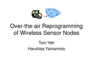
Remote Data Collection for Wireless Sensor Networks (WSNs) • We address the specific problem of range extension of wireless sensor nodes that may have to communicate to a remote collection center • Due to the significant range, such sensors do not have line-of-sight to the collector and, furthermore, the collector may be mobile • This results in fast fading
Use of Space-Time Coding to Provide Resistance to Fast-Fading in Non LOS • We seek a MIMO architecture that can provide diversity without feedback from a collection point • This allows us to operate in highly mobile scenarios • Orthogonal space-time block codes (OSTBCs) do not require channel state information (CSI) to be sent back from the collector • We seek full diversity codes with possible reductions in rate, e.g., Tarokh • For the Alamouti code, consider two transmit and one receive antenna with the received signals at subsequent time periods being • Detector outputs use combinations of both channels • As additional channels are added there is reduced probability of outage
Motivation: Diversity Increases Probability of Packet Success • Packet success as a function of range for different numbers of sensor nodes • Collector is assumed to have one antenna element • Node transmit power of 20 dBm • Receiver sensitivity of -105 dBm • Background noise of -114 dBm/MHz • Free-space loss exponent of 2.8 • Binary-phase shift-keying (BPSK) modulation at a rate of 500 kbps • Carrier frequency of 1350 MHz with a packet size of one kByte • Collection platform speed is set at 100 miles/hour • Jakes fading model • There is a significant range extension that can be achieved
Signal Model • With Nc collector antenna elements, the received collector signal rc(t) 2 CNc on the uplink is given in continuous-time by • The term represents additive white Gaussian noise with individual terms having variance 2 • The symbols sk(m) represent a training sequence in the estimation phase, or the m-th row and k-th column of an OSTBC matrix • The pulses p(t) are raised-cosine with minimal excess bandwidth to maximize orthogonality where is the channel from sensor k to the collector, Es is the symbol energy k is the frequency offset in Hz for sensor k, and k is the corresponding delay
Illustration of Parameter Estimates • Challenging parameter estimates are the frequency offsets • Synchronization must happen during transmission in order to exploit the OSTBC • Can be achieved with a start packet sent from collector • High oversampling and real-time processing in FPGA allow accurate timing
Time and Frequency Offset Estimation • In forming the detector, consider a new set of symbols formed by the conjugate pairs of received samples (ND is oversampling rate) • We note that if sampled at the symbol rate, and aligned with the peak of the pulse shape q(0), the resulting received signal can be simplified to • If proper timing alignment is achieved, the conjugate pair becomes where are the conjugate pairs of received symbols and is the product of two independent circular Gaussians
Time and Frequency Offset Estimation (cont.) • We can collect a set of these homodyne symbols corresponding to one less than the length of the training sequence • We see that if the symbols d(n) were known then a correlation would result and associated carrier offset formed • For this purpose we create a set of conjugate training symbol pairs where and are a known set of training symbols. • In forming the correlation , a peak will indicate the time offset • It is at this point that the carrier offset is recorded
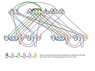
Packet Structure and Associated Receiver Structure Xmtr 1 Xmtr 2 Symbol Period (Time) Xmtr 1: Training Symbols w/ Interleaved 0s Xmtr 1: Data Symbols Carrier Frequency: fc1 = fc MHz + Df1 Compare correlation magnitudes – select higher value to determine timing Homodyne for Xmtr 1 Training Symbols Space-time decoding and remaining receiver functions UNEQUAL RANDOM CARRIER FREQ OFFSETS:Df1≠Df2 Analog Rcvr A/D DDC Homodyne for Xmtr 2 Training Symbols Carrier Frequency: fc2 = fc MHz + Df2 Xmtr 2: Data Symbols Xmtr 2: Training Symbols w/ Interleaved 0s
Channel Estimation and Residual Carrier Offset Correction • After timing estimation and associated downsampling, the resulting received signal model is given by where with individual terms • The term represents the residual carrier offset error • We note there is both a time varying channel (hk(l)), due to mobility, as well as a constant effective Doppler shift (ej l) due to inaccuracies in the carrier offset estimation block. • In order to track the time-varying channel, there are several possible approaches • One of the highest performers is to employ a Kalman filter (KF) using a second-order autoregressive (AR2) process • Costly in terms of hardware, particularly for a high data rate system
Least Mean Square (LMS) Channel Tracking • We seek a channel tracker that offers low computational complexity and can be performed recursively • Filters, such as least mean square (LMS), offer this utility while still obtaining good performance • For such an solution we consider the cost • Seeking a recursive implementation that can not only estimate the channel with multiple training symbols, but also track the channel in decision-directed (DD) mode, we can form the LMS filter where
Variable LMS (vLMS) • One of the drawbacks of the classic LMS implementation is the fact that the step size is constant • In most packet-based systems there will be both a training period as well as a data packet period • Intuitively, one solution would be to have different values for during each period • But, there is the additional issue that during the first few symbols of the training packet there will be a much larger error than at the end of the training period • For this reason, we employ the variable step-size LMS (vLMS) algorithm proposed by Aboulnasr and Mayyas • Here, the update expression for the step size is given by where MSE = e*(l)e(l), 2 (0,1] and > 0
Channel Tracking Simulation Results • In the simulations we compare the vLMS architecture to the AR2-KF channel tracker as well as the case where the channel is known • As can be seen from the figure, vLMS offers worse performance than the AR2-KF architecture, but is still acceptable • The vLMS algorithm is able to be readily realized in hardware. • The vLMS parameters are = .99 and = .001 • The channels are normalized such that the maximum value of the channel response is equal in magnitude to the transmitted symbol
System Generator Architecture for One of the Receive Paths Peak search and time/frequency offset estimation Quadrature downconversion and pulse-shape filtering Conjugate symbol formation and correlation vLMS channel tracking and symbol decoding ADC input
Receiver FPGA Resource Use • The transceiver has been targeted to a Xilinx Virtex-4SX35 FPGA • The clocking frequency of the device is 64 MHz • As can be seen from the table, functions related to time and frequency offset estimation represent the highest use of resources • Buffering for producing the correlator output and performing the peak search require a significant amount of memory • We currently use on chip dual-port block RAM in order to maximize throughput
Toyon’s Modular MIMO (ModMIMO) Testbed • The RF portion of our testbed is designed to provide flexibility over both phase and frequency coherency • A set of common IF/RF mixing signals are generated on a base board and feed each RF board with coherent signals • This represents the least challenging arrangement in terms of signal processing – both for timing and frequency estimation • With the modular design, single antenna nodes can be prototyped by having their own VCO-RF board pair • One important element of our design is our choice of voltage control oscillator • We are using a Vectron temperature compensated crystal with ±1.5 ppm stability over -20 C to +70 C and ±5.0 ppm over -40 C to +85 C • Frequency offset affects our search space for that parameter estimate
Four-Antenna Capable Testbed • Designed as a research and development platform • Operates at 915 MHz • Leverages an Avnet V4SX35 motherboard • Variety of interfaces, including UART, USB, and Ethernet • Connector, VCO, and RF translation boards were all designed in house • Fabbed and populated by outside partner • Individual components representative of fieldable hardware and can be readily translated to a final design
Conclusion • We have presented a distributed OSTBC technique that can be used to increase the link reliability of wireless nodes, particularly when transmitting over long range with NLOS conditions • While able to reduce the necessary link margin, through channel diversity, there are several technical challenges • Nodes no longer share a common crystal - We lose synchronization over carrier frequency • As the medium access control (MAC) layer is not synchronized, there are special timing considerations that must be made • Our solution for this problem is to use a high oversampling rate and employ training sequences to make accurate time/frequency offset estimates • Accurate time resolution provides good synchronization • A minimum of orthogonalization is lost between code pairs • We note that use of an OSTBC requires the nodes to share a common set of data • Data can be shared if assumed that local wireless communication is essentially free – Ratio of long- to short-range power output high