Download
1 / 16
540 likes | 2.21k Vues
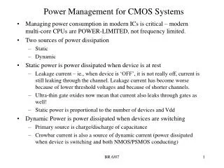
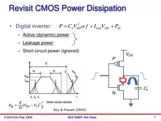
Two Components contribute to the power dissipation: Static Power Dissipation Leakage current Sub-threshold current Dynamic Power Dissipation Short circuit power dissipation Charging and discharging power dissipation. Power Dissipation in CMOS. Static Power Dissipation. VDD.

E N D
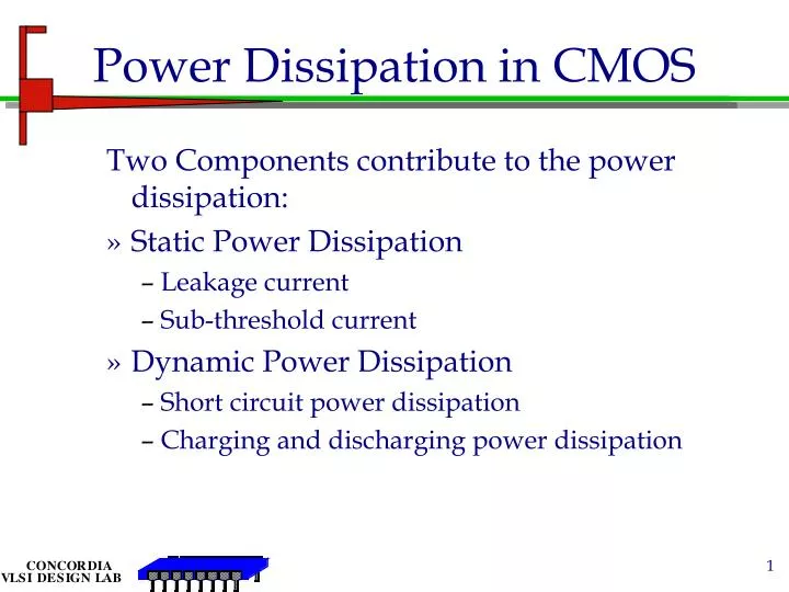
Two Components contribute to the power dissipation: Static Power Dissipation Leakage current Sub-threshold current Dynamic Power Dissipation Short circuit power dissipation Charging and discharging power dissipation Power Dissipation in CMOS
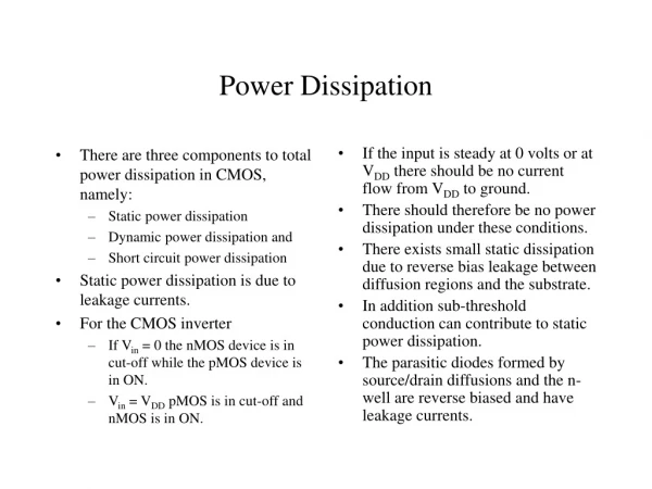
Static Power Dissipation VDD • Leakage Current: • P-N junction reverse biased current: • io= is(eqV/kT-1) • Typical value 0.1nA to 0.5nA @room temp. • Total Power dissipation: • Psl= i0.VDD • Sub-threshold Current • Relatively high in low threshold devices S G B MP D Vin Vo D G B MN S GND
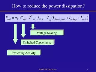
Analysis of CMOS circuit power dissipation • The power dissipation in a CMOS logic gate can be • expressed as • P = Pstatic + Pdynamic • = (VDD · Ileakage) + (p · f · Edynamic) • Where p is the switching probability or activity factor • at the output node (i.e. the average number of output • switching events per clock cycle). • The dynamic energy consumed per output switching event is defined as Edynamic =
Analysis of CMOS circuit power dissipation The first term —— the energy dissipation due to the Charging/discharging of the effective load capacitance CL. The second term —— the energy dissipation due to the input-to-output coupling capacitance. A rising input results in a VDD-VDD transition of the voltage across CM and so doubles the charge of CM. CL = Cload + Cdbp +Cdbn CM = Cgdn + Cgdp
The MOSFET parasitic capacitances • • distributed, • • voltage-dependent, and • • nonlinear. • So their exact modeling is quite complex. Even ESC can be modeled, it is also difficult to calculate the Edynamic. On the other hand, if the short-circuit current iSC can be Modeled, the power-supply current iDD may be modeled with the same method. So there is a possibility to directly model iDD instead of iSC.
Analysis of short-circuit current The short-circuit energy dissipation ESC is due to the rail-to-rail current when both the PMOS and NMOS devices are simultaneously on. ESC = ESC_C + ESC_n Where and
Charging and discharging currents • Discharging Inverter Charging Inverter
Factors that affect the short-circuit current For a long-channel device, assuming that the inverter is symmetrical (n = p = and VTn = -VTp = VT) and with zero load capacitance, and input signal has equal rise and fall times (r = f = ), the average short-circuit current [Veendrick, 1994] is From the above equation, some fundamental factors that affect short-circuit current are: , VDD, VT, and T.
Parameters affecting short cct current For a short-channel device, and VT are no longer constants, but affected by a large number of parameters (i.e. circuit conditions, hspice parameters and process parameters). CL also affects short-circuit current. Imean is a function of the following parameters (tox is process-dependent): CL, , T (or /T), VDD, Wn,p, Ln,p (or Wn,p/Ln,p ), tox, … The above argument is validated by the means of simulation in the case of discharging inverter,