Download
1 / 21
210 likes | 315 Vues
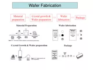
Fabrication II. By Ryan Sharp a nd Andrew Keisic. Topics. How to machine a simple part. Things to Keep in Mind When Designing Parts Tooling Setup CNC. How would you machine this simple part?. Step 1. Acquire material. (Aluminum 6065). Step 2.

E N D
Fabrication II By Ryan Sharp and Andrew Keisic
Topics • How to machine a simple part. • Things to Keep in Mind When Designing Parts • Tooling • Setup • CNC
Step 1 • Acquire material. (Aluminum 6065)
Step 2 • Using the Vertical mill square up the stock. (Make the sides straight and perpendicular) Clamp the stock in the vise
Step 3 • Machine stock to correct size. 1. Measure length and subtract the dimension you want from the dimension you measured. 2. This is the distance to need to travel to remove the correct amount of material 3. Repeat steps 1 and 2 for the width of the part.
Step 4 • Drill the three holes on the face. 1. Use an edge finder to find the edge of the part. 2. Move left or right to find the correct hole location 3. Center drill 4. Drill 5. Repeat steps 2-4 for the other holes
Step 5 • Reposition part so you can drill and tap the hole for the set screw. • First find the location of the hole using an edge finder • Center Drill • Drill the hole for an 8-32 tap (.1575-.1850 Drill) • Tap with an 8-32 tap
Step 6 • Deburr(Remove sharp edges) • Use a file. • Use a deburr tool.
Step 7 • Inspect (check dimensions)
Things to Keep in Mind When Designing Parts • How would you machine these types of parts? • What is a good medium between strength and machining feasibility? • Does this part need all of those cool radii and contours?
Tooling Lathe Tooling Vertical Mill Tooling
Setups T slots
CNC- Computer Numerical Control Main types of programming Shop Floor/Tool Room G-Code Master CAM/ CAD CAM
Shop Floor/Tool Room • Type in Parameters
G-Code • The G-codes are the codes that position the tool and do the actual work, as opposed to M-codes, that manages the machine; T for tool-related codes. S and F are tool-Speed and tool-Feed.
G-Code • % • N1 O003 (DIAMOND SQUARE) • N2 G54 G90 G49 G80 • N3 M6 T1 (1.ENDMILL) • N4 M3 S1800 • N5 G0 X-.6 Y2.050 • N6 G43 H1 Z.1 • N7 G1 Z-.3 F50. • N8 G41 D1 Y1.45 • N9 G1 X0 F20. • N10 G2 J-1.45 • N11 G1 X.1 • N12 G0 Z.1 • N13 G40 • N14 G0 X-1.590 Y1.590 • N15 G1 Z-.2 F50. • N16 G41 D1 Y.990 • N17 G1 X.990 F20. • N18 Y-.990 • N19 X-.990 • N20 Y1.09 • N21 G0 Z.1 • N22 G40 • N23 G0 X-.6 Y1.590 • N24 G1 Z-.1 F50. • N25 G41 D1 Y.990 • N26 G1 X0 F20. • N27 X.75 Y0 • N28 X0 Y-.990 • N29 X-.75 Y0 • N30 X0 Y.990 • N31 X.1 • N31 G0 Z.1 • N32 G40 • N33 M5 G49 G28 G91 Z0 • N34 M3 • %
Master CAM/ CAD CAM • Import CAD File • Select tool paths and other variables. • The software generates G-Code. • Transfer G-Code to CNC Machine
Master CAM Shows tool paths so you can see any possible mistakes before you cut any material