Download
1 / 6
70 likes | 244 Vues
Wiring Diagram. Solar panel or charger. SDM-CD16AC address #1: A=0, B=0 #2: A=1, B=2. 1. 2. 2. 1. 4x16. Colored wires to control line at irrigation valve solenoid (one for each valve).

E N D
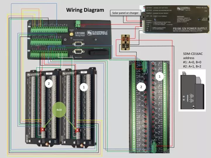
Wiring Diagram Solar panel or charger SDM-CD16AC address #1: A=0, B=0 #2: A=1, B=2 1 2 2 1 4x16
Colored wires to control line at irrigation valve solenoid (one for each valve) 1 2 3 4 5 6 7 8 9 10 11 12 13 14 15 16 #1 SDM address must be set to 0 #2 SDM address must be set to 1 32 31 30 29 28 27 26 25 24 23 22 21 20 19 18 17 White wire to common at solenoid power (25VAC in USU Greenville Farm)
Multiplexer to loadcell wiring Loadcell 16 2 1 Must be set to 4 x 16 To loadcell signal low To loadcell signal high To loadcellground To loadcellvoltage in
Treatments(assigned randomly): well watered (1.2 x ET) mild drought (0.8 x ET) severe drought (0.6 x ET) extra North Experimental layout for 2012 Greenville Farm Single species - 3 water treatments This is an example that matches the program in the manual Multiple species and water treatments can be accommodated 1 12 23 24 13 2 25 3 14 4 15 26 5 26 16 17 6 27 28 18 7 19 8 29 9 20 30 21 10 32 null 22 11 Notes: Once treatments are assigned, the multiplexer and relay driver (SDM-CD16AC) must be rewired in the order of the treatments. For the above example, trees 1,2,6,10,14,15,17,19,21,25,27,&32 are wired into multiplexer 1 channels 1-12; and irrigation valves 1,2,6,10,14,15,17,19,21,25,27,&32 are wired into relay driver 1 channels 1-12. trees 6 and 14 are extra and included in the well watered treatment in this example. They could be assigned to other treatments. Trees 3,4,8,11,16,20,23,26,29 & 30 are wired into multiplexer 1 channels 13-16 & multiplexer 2 channels 1-6; and irrigation valves 3,4,8,11,16,20,23,26,29 & 30 are wired into relay driver 1 channels 13-16 & relay driver 2 channels 1-6. Trees 5,7,9,12,13,18,22,24, 26 & 28 are wired into multiplexer 2 channels 7-16; and irrigation valves 5,7,9,12,13,18,22,24, 26 & 28 are wired into relay driver 2 channels 7-16.