Download
1 / 9
90 likes | 181 Vues
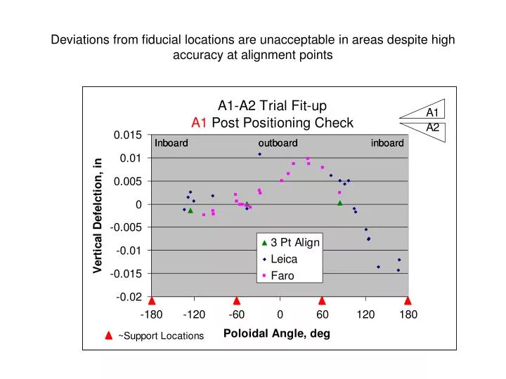
Deviations from fiducial locations are unacceptable in areas despite high accuracy at alignment points. In particular, the mating flanges do not track each other. A2, the coil mounted directly on the fixture, maintains its shape in the z-direction.

E N D
Deviations from fiducial locations are unacceptable in areas despite high accuracy at alignment points
In particular, the mating flanges do not track each other • A2, the coil mounted directly on the fixture, maintains its shape in the z-direction. • We would expect that, with the coils properly mated, the “A”. • The mating flanges clearly do not track each other after shimming and torquing. • “A1 flg A nopaper” is the measured fiducials on A1 flange A, minus .005” to compensate for Fuji paper that was present.
We may have locked in these deviations as a result of our choice of shim thickness • Flange gaps were measured after positioning at inside and outside edges. • The calculated shim thickness was derived from flange scans and MCWF fiducial measurement prior to positioning. • The “compensated” shim thicknesses are the calculated shim thicknesses, with the average initial z-adjustment that was required [.008”] added.
The difference between calculated [and compensated] shim thickness, and the measured thickness chosen, tracks the deviation on the A1 flange in the worst areas. Compare “gap_comp” with “dz_nopaper”.
Initial modular coil measurements [ required for each modular coil]: Set the modular coil on the fixture, “B” flange down Using the laser tracker, align to the conical seats. It is necessary to achieve a RMS deviation on .005” or better during the lock-in. Measure the monuments on the fixture in order to establish a global coordinate system that we can return to. Some additional monuments on the walls may be included. This will establish a global coordinate system based on the modular coil geometry. Measure all of the tooling ball monuments on the winding form. The laser will need to be moved around the perimeter of the part. The final set of measurements must overlap the initial set of measurements. The difference between repeated measurements of the same tooling balls must be .005” or less. Scan the “A” flange of the modular coil. A-A modular coil fitup: Prerequisite: the shim thicknesses at all locations shall have been calculated based on “A” flange scan data from the previous step. Position the first type A modular coil on the fixture, “B” flange down. Obtain a set of “realigned” fiducial positions. Align the laser tracker to the tooling balls on the “A” flange. A rms deviation of less than .005” is required. Measure the monuments on the fixture, and some on the walls, in order to establish a global coordinate system based on the modular coil geometry. Place the initial three shims on the coil in the designated locations, identical to those in the A1-A2 fitup test. Install dial indicators on the modular coil in areas where we expect to see deflection. This may be less of an issue with the MTM fixtures that we will use for actual assembly. Flange measurements can be used to optimize shim thickness while minimizing the cost and schedule impact. A sample assembly sequence is shown below.
Lower the mating type A modular coil into position. Measure the monuments on the bottom coil. Use jacks as needed to bring displaced monuments back to within .002” of their original position. The dial indicators can be used to help with this process. Using three target points, perform the positioning as was done in the A1-A2 fitup test. If a z-adjustment is required, use the average of the adjustments to derive a “compensated calculated” set of shims. Install the shims , install studs, bushings, supernuts, and torque to 50% of final value. Measure the tooling balls on both coils. The maximum deviation from the “realigned” points should be .007” or less. Re-measure the tooling balls on both coils. If not, loosen all studs, adjust shims locally. Re-torque all studs to 50%. Complete tightening of flange bolts. Install eccentric bushings at three stud locations in order to preserve the relative coil positions after disassembly. Remove all studs, nuts, shims etc. Identify shim locations. A-B modular coil assembly: Place the “A” coil, “A” flange down, on the 20deg fixture. Obtain a set of “realigned” fiducial positions for the “A” and “B” coils. Align the laser tracker to the tooling balls on the coil. RMS deviation should be .005” or better. Measure the monuments on the fixture, and some on the walls, to establish a global system based on the modular coil coordinate system. Scan the “B” flange. Calculate the required shim thicknesses at all stud locations and the nose region. Place three initial shims on the coil’s “A” flange in designated locations. [similar to the A1-A2 fitup test] Lower the B coil onto the A coil. Measure the monuments on the A coil. Jack areas of the coil as necessary to bring displaced monuments back to within .002” of their original position. Sample assembly sequence [continued]
Using three target points, perform the positioning as was done in the A1-A2 fitup test. If a z-adjustment is required, use the average of the adjustments to derive a “compensated calculated” set of shims. Install the shims , install studs, bushings, supernuts, and torque to 50% of final value. Measure the tooling balls on both coils. The maximum deviation from the “realigned” points should be .007” or less. If not, loosen all studs, adjust shims locally. Re-torque all studs to 50%. Measure the tooling balls on both coils. The maximum deviation from the “realigned” points should be .007” or less. Complete tightening of flange bolts. Measure the tooling balls on both coils. The maximum deviation from the “realigned” points should be .007” or less. Scan the “B” flange of the “B” coil. (A+B) to C modular coil assembly: Place the “AB” assembly, “A” coil down, on the 40deg fixture. Obtain a set of “realigned” fiducial positions. For the “A”, “B”, and “C” coils. Align the laser tracker to the tooling balls on the “A” coil. RMS deviation should be .005” or better. Measure the monuments on the fixture, and some on the walls, to establish a global system based on the modular coil coordinate system. Calculate the required shim thicknesses at all stud locations and the nose region. Place three initial shims on the “B” coil “B” flange in designated locations. [similar to the A1-A2 fitup test] Lower the C coil onto the B coil. Using three target points, perform the positioning as was done in the A1-A2 fitup test. If a z-adjustment is required, use the average of the adjustments to derive a “compensated calculated” set of shims. Sample assembly sequence [continued]
Install the shims , install studs, bushings, supernuts, and torque to 50% of final value. Measure the tooling balls on both coils. The maximum deviation from the “realigned” points should be .007” or less. If not, loosen all studs, adjust shims locally. Re-torque all studs to 50%. Measure the tooling balls on both coils. The maximum deviation from the “realigned” points should be .007” or less. Complete tightening of flange bolts. Measure the tooling balls on both coils. The maximum deviation from the “realigned” points should be .007” or less. Scan the “B” flange of the “C” coil. Sample assembly sequence [continued]