Download
1 / 77
7.74k likes | 15.71k Vues
WELDING PROCESSES. Arc Welding Resistance Welding Oxyfuel Gas Welding Other Fusion Welding Processes Solid State Welding Weld Quality Weldability. Two Categories of Welding Processes.

E N D
WELDING PROCESSES • Arc Welding • Resistance Welding • Oxyfuel Gas Welding • Other Fusion Welding Processes • Solid State Welding • Weld Quality • Weldability
Two Categories of Welding Processes • Fusion welding - coalescence is accomplished by melting the two parts to be joined, in some cases adding filler metal to the joint • Examples: arc welding, resistance spot welding, oxyfuel gas welding • Solid state welding - heat and/or pressure are used to achieve coalescence, but no melting of base metals occurs and no filler metal is added • Examples: forge welding, diffusion welding, friction welding
Arc Welding (AW) A fusion welding process in which coalescence of the metals is achieved by the heat from an electric arc between an electrode and the work • Electric energy from the arc produces temperatures ~ 10,000 F (5500 C), hot enough to melt any metal • Most AW processes add filler metal to increase volume and strength of weld joint
What is an Electric Arc? An electric arc is a discharge of electric current across a gap in a circuit • It is sustained by an ionized column of gas (plasma) through which the current flows • To initiate the arc in AW, electrode is brought into contact with work and then quickly separated from it by a short distance
Arc Welding A pool of molten metal is formed near electrode tip, and as electrode is moved along joint, molten weld pool solidifies in its wake Figure 31.1 Basic configuration of an arc welding process.
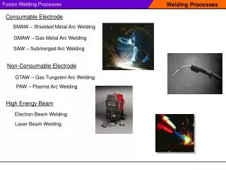
Two Basic Types of AW Electrodes • Consumable – consumed during welding process • Source of filler metal in arc welding • Nonconsumable – not consumed during welding process • Filler metal must be added separately
Consumable Electrodes • Forms of consumable electrodes • Welding rods (a.k.a. sticks) are 9 to 18 inches and 3/8 inch or less in diameter and must be changed frequently • Weld wire can be continuously fed from spools with long lengths of wire, avoiding frequent interruptions • In both rod and wire forms, electrode is consumed by arc and added to weld joint as filler metal
Nonconsumable Electrodes • Made of tungsten which resists melting • Gradually depleted during welding (vaporization is principal mechanism) • Any filler metal must be supplied by a separate wire fed into weld pool
Arc Shielding • At high temperatures in AW, metals are chemically reactive to oxygen, nitrogen, and hydrogen in air • Mechanical properties of joint can be seriously degraded by these reactions • To protect operation, arc must be shielded from surrounding air in AW processes • Arc shielding is accomplished by: • Shielding gases, e.g., argon, helium, CO2 • Flux
Flux A substance that prevents formation of oxides and other contaminants in welding, or dissolves them and facilitates removal • Provides protective atmosphere for welding • Stabilizes arc • Reduces spattering
Various Flux Application Methods • Pouring granular flux onto welding operation • Stick electrode coated with flux material that melts during welding to cover operation • Tubular electrodes in which flux is contained in the core and released as electrode is consumed
Power Source in Arc Welding • Direct current (DC) vs. Alternating current (AC) • AC machines less expensive to purchase and operate, but generally restricted to ferrous metals • DC equipment can be used on all metals and is generally noted for better arc control
Consumable Electrode AW Processes • Shielded Metal Arc Welding • Gas Metal Arc Welding • Flux‑Cored Arc Welding • Electrogas Welding • Submerged Arc Welding
Shielded Metal Arc Welding (SMAW) Uses a consumable electrode consisting of a filler metal rod coated with chemicals that provide flux and shielding • Sometimes called "stick welding" • Power supply, connecting cables, and electrode holder available for a few thousand dollars
Shielded Metal Arc Welding Figure 31.3 Shielded metal arc welding (SMAW).
Shielded Metal Arc Welding Figure 31.2 Shielded metal arc welding (stick welding) performed by a (human) welder (photo courtesy of Hobart Brothers Co.).
SMAW Applications • Used for steels, stainless steels, cast irons, and certain nonferrous alloys • Not used or rarely used for aluminum and its alloys, copper alloys, and titanium
Gas Metal Arc Welding (GMAW) Uses a consumable bare metal wire as electrode and shielding accomplished by flooding arc with a gas • Wire is fed continuously and automatically from a spool through the welding gun • Shielding gases include inert gases such as argon and helium for aluminum welding, and active gases such as CO2 for steel welding • Bare electrode wire plus shielding gases eliminate slag on weld bead - no need for manual grinding and cleaning of slag
Gas Metal Arc Welding Figure 31.4 Gas metal arc welding (GMAW).
GMAW Advantages over SMAW • Better arc time because of continuous wire electrode • Sticks must be periodically changed in SMAW • Better use of electrode filler metal than SMAW • End of stick cannot be used in SMAW • Higher deposition rates • Eliminates problem of slag removal • Can be readily automated
Flux‑Cored Arc Welding (FCAW) Adaptation of shielded metal arc welding, to overcome limitations of stick electrodes • Electrode is a continuous consumable tubing (in coils) containing flux and other ingredients (e.g., alloying elements) in its core • Two versions: • Self‑shielded FCAW - core includes compounds that produce shielding gases • Gas‑shielded FCAW - uses externally applied shielding gases
Flux-Cored Arc Welding Figure 31.6 Flux‑cored arc welding. Presence or absence of externally supplied shielding gas distinguishes the two types: (1) self‑shielded, in which core provides ingredients for shielding, and (2) gas‑shielded, which uses external shielding gases.
Electrogas Welding (EGW) Uses a continuous consumable electrode, either flux‑cored wire or bare wire with externally supplied shielding gases, and molding shoes to contain molten metal • When flux‑cored electrode wire is used and no external gases are supplied, then special case of self‑shielded FCAW • When a bare electrode wire used with shielding gases from external source, then special case of GMAW
Electrogas Welding Figure 31.7 Electrogas welding using flux‑cored electrode wire: (a) front view with molding shoe removed for clarity, and (b) side view showing molding shoes on both sides.
Submerged Arc Welding (SAW) Uses a continuous, consumable bare wire electrode, with arc shielding provided by a cover of granular flux • Electrode wire is fed automatically from a coil • Flux introduced into joint slightly ahead of arc by gravity from a hopper • Completely submerges operation, preventing sparks, spatter, and radiation
Submerged Arc Welding Figure 31.8 Submerged arc welding.
SAW Applications and Products • Steel fabrication of structural shapes (e.g., I‑beams) • Seams for large diameter pipes, tanks, and pressure vessels • Welded components for heavy machinery • Most steels (except hi C steel) • Not good for nonferrous metals
Non-consumable Electrode Processes • Gas Tungsten Arc Welding • Plasma Arc Welding • Carbon Arc Welding • Stud Welding
Gas Tungsten Arc Welding (GTAW) Uses a non-consumable tungsten electrode and an inert gas for arc shielding • Melting point of tungsten = 3410C (6170F) • A.k.a. Tungsten Inert Gas (TIG) welding • In Europe, called "WIG welding" • Used with or without a filler metal • When filler metal used, it is added to weld pool from separate rod or wire • Applications: aluminum and stainless steel most common
Gas Tungsten Arc Welding Figure 31.9 Gas tungsten arc welding.
Advantages / Disadvantages of GTAW Advantages: • High quality welds for suitable applications • No spatter because no filler metal through arc • Little or no post-weld cleaning because no flux Disadvantages: • Generally slower and more costly than consumable electrode AW processes
Plasma Arc Welding (PAW) Special form of GTAW in which a constricted plasma arc is directed at weld area • Tungsten electrode is contained in a nozzle that focuses a high velocity stream of inert gas (argon) into arc region to form a high velocity, intensely hot plasma arc stream • Temperatures in PAW reach 28,000C (50,000F), due to constriction of arc, producing a plasma jet of small diameter and very high energy density
Plasma Arc Welding Figure 31.10 Plasma arc welding (PAW).
Advantages / Disadvantages of PAW Advantages: • Good arc stability • Better penetration control than other AW • High travel speeds • Excellent weld quality • Can be used to weld almost any metals Disadvantages: • High equipment cost • Larger torch size than other AW • Tends to restrict access in some joints
Resistance Welding (RW) A group of fusion welding processes that use a combination of heat and pressure to accomplish coalescence • Heat generated by electrical resistance to current flow at junction to be welded • Principal RW process is resistance spot welding (RSW)
Resistance Welding Figure 31.12 Resistance welding, showing the components in spot welding, the main process in the RW group.
Components in Resistance Spot Welding • Parts to be welded (usually sheet metal) • Two opposing electrodes • Means of applying pressure to squeeze parts between electrodes • Power supply from which a controlled current can be applied for a specified time duration
Advantages / Drawbacks of RW Advantages: • No filler metal required • High production rates possible • Lends itself to mechanization and automation • Lower operator skill level than for arc welding • Good repeatability and reliability Disadvantages: • High initial equipment cost • Limited to lap joints for most RW processes
Resistance Spot Welding (RSW) Resistance welding process in which fusion of faying surfaces of a lap joint is achieved at one location by opposing electrodes • Used to join sheet metal parts using a series of spot welds • Widely used in mass production of automobiles, appliances, metal furniture, and other products made of sheet metal • Typical car body has ~ 10,000 spot welds • Annual production of automobiles in the world is measured in tens of millions of units
Spot Welding Cycle Figure 31.13 (a) Spot welding cycle, (b) plot of squeezing force & current in cycle (1) parts inserted between electrodes, (2) electrodes close, force applied, (3) current on, (4) current off, (5) electrodes opened.
Resistance Seam Welding (RSEW) Uses rotating wheel electrodes to produce a series of overlapping spot welds along lap joint • Can produce air‑tight joints • Applications: • Gasoline tanks • Automobile mufflers • Various other sheet metal containers
Resistance Seam Welding Figure 31.15 Resistance seam welding (RSEW).
Resistance Projection Welding (RPW) A resistance welding process in which coalescence occurs at one or more small contact points on parts • Contact points determined by design of parts to be joined • May consist of projections, embossments, or localized intersections of parts
Resistance Projection Welding Figure 31.17 Resistance projection welding (RPW): (1) start of operation, contact between parts is at projections; (2) when current is applied, weld nuggets similar to spot welding are formed at the projections.
Oxyfuel Gas Welding (OFW) Group of fusion welding operations that burn various fuels mixed with oxygen • OFW employs several types of gases, which is the primary distinction among the members of this group • Oxyfuel gas is also used in flame cutting torches to cut and separate metal plates and other parts • Most important OFW process is oxyacetylene welding
Oxyacetylene Welding (OAW) Fusion welding performed by a high temperature flame from combustion of acetylene and oxygen • Flame is directed by a welding torch • Filler metal is sometimes added • Composition must be similar to base metal • Filler rod often coated with flux to clean surfaces and prevent oxidation
Oxyacetylene Welding Figure 31.21 A typical oxyacetylene welding operation (OAW).
Acetylene (C2H2) • Most popular fuel among OFW group because it is capable of higher temperatures than any other ‑ up to 3480C (6300F) • Two stage chemical reaction of acetylene and oxygen: • First stage reaction (inner cone of flame): C2H2 + O2 2CO + H2 + heat • Second stage reaction (outer envelope): 2CO + H2 + 1.5O2 2CO2 + H2O + heat
Oxyacetylene Torch • Maximum temperature reached at tip of inner cone, while outer envelope spreads out and shields work surfaces from atmosphere Figure 31.22 The neutral flame from an oxyacetylene torch indicating temperatures achieved.
Alternative Gases for OFW • Methylacetylene‑Propadiene (MAPP) • Hydrogen • Propylene • Propane • Natural Gas