Download
1 / 23
260 likes | 336 Vues
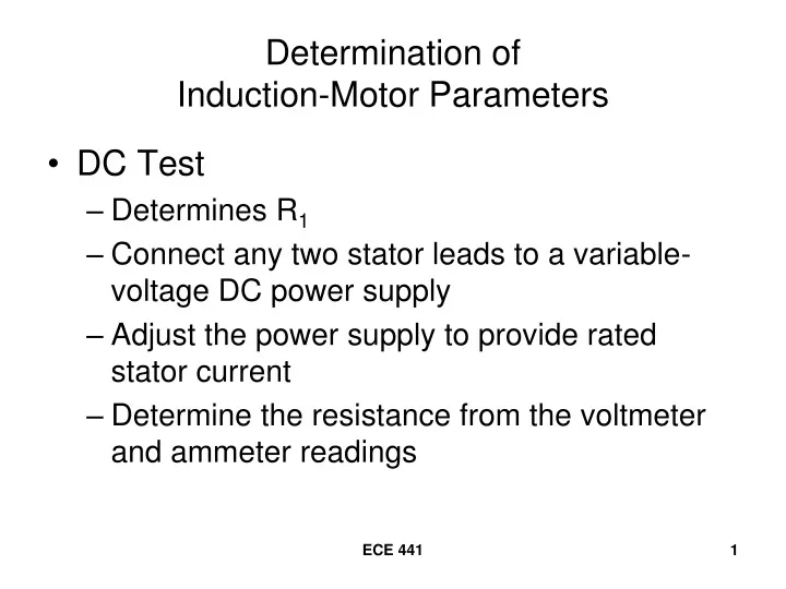
Determination of Induction-Motor Parameters. DC Test Determines R 1 Connect any two stator leads to a variable-voltage DC power supply Adjust the power supply to provide rated stator current Determine the resistance from the voltmeter and ammeter readings. For a Y-Connected Stator.

E N D
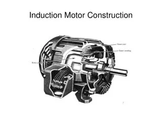
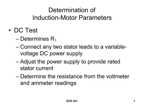
Determination of Induction-Motor Parameters • DC Test • Determines R1 • Connect any two stator leads to a variable-voltage DC power supply • Adjust the power supply to provide rated stator current • Determine the resistance from the voltmeter and ammeter readings ECE 441
For a Y-Connected Stator ECE 441
For a Delta-Connected Stator ECE 441
Determination of Induction-Motor Parameters • Blocked-Rotor Test • Determine X1 and X2 • Determines R2 when combined with data from the DC Test • Block the rotor so that it will not turn • Connect to a variable-voltage AC supply and adjust until the blocked-rotor current is equal to the rated current ECE 441
Simplified Equivalent Circuit Neglect the exciting current under blocked-rotor conditions – remove the parallel branch ECE 441
IEEE test code recommends that the blocked-rotor test be made using 25% rated frequency with the test voltage adjusted to obtain approximately rated current. A 60-Hz motor would use a 15-Hz test voltage. The calculated reactance is corrected to 60-Hz by multiplying by 60/15. Calculated resistance is correct. ECE 441
How Is the Blocked-Rotor Impedance Divided? If the NEMA-design letter of the motor is known, use Table 5.10 to divide the impedances. Otherwise, divide the impedances equally. ECE 441
Determination of Induction-Motor Parameters • No-Load Test • Determine the magnetizing reactance, XM and combined core, friction, and windage losses. • Connect as for blocked-rotor test (next slide). • The rotor is unblocked and allowed to run unloaded at rated voltage and rated frequency. ECE 441
Electrical connection for the No-Load Test is the same as for the Blocked-Rotor Test ECE 441
Determination of Induction-Motor Parameters • At no-load, the speed is very close to synchronous speed – the slip is =0, causing the current in R2/s to be very small, and will be ignored i the calculations. • IM>>Ife, so I0 = IM. ECE 441
The equivalent circuit for the no-load test is shown. Ignore ECE 441
Substitute X1 from the blocked-rotor test to determine the value of XM. ECE 441
Example 5.16 • The following data were obtained from no-load, blocked-rotor, and DC tests of a three-phase, wye-connected, 40-hp, 60-Hz, 460-V, design B induction motor whose rated current is 57.8A. The blocked-rotor test was made at 15 Hz. ECE 441
Blocked-Rotor No-Load DC Vline = 36.2V Vline = 460.0V VDC = 12.0V Iline = 58.0A Iline = 32.7A IDC = 59.0A P3phase = 2573.4W P3phase = 4664.4W a) Determine R1, X1, R2, X2, XM, and the combined core, friction, and windage loss. b) Express the no-load current as a percent of rated current. ECE 441
Convert the AC test data to corresponding phase values for a wye-connected motor. ECE 441
Determine R1 Determine R2 ECE 441
Determination of X1 and X2 From Table 5.10, for a design B machine, X1 = 0.4XBR,60 = 0.4(1.0182) = 0.4073Ω/phase X2 = 0.6XBR,60 = 0.6(1.0182) = 0.6109/phase ECE 441
Determination of XM ECE 441
Determination of combined friction, windage, and core loss: b) Express the no-load current as a percent of rated current. ECE 441