Download

1 / 15
200 likes | 503 Vues
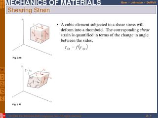
Strain Gages . By Dr. Sotiris Omirou. Strain-gauge . The electrical resistance strain is a metal wire or metal foil strip which is wafer-like and can be stuck onto surfaces like a postage stamp. . Typical bonded strain gages.

E N D
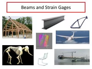
Strain Gages By Dr. Sotiris Omirou
Strain-gauge The electrical resistance strain is a metal wire or metal foil strip which is wafer-like and can be stuck onto surfaces like a postage stamp.
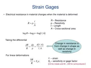
When a strain gauge is bonded to an object, and the object changes in size, the resistance of the strain gauge will change. The resistance R is given by the expression: R= ρ l/A Where: • l is the length of the wire in meters • ρ is the resistivity of the material in ohm meters • A is the cross-sectional area of the filament in m2
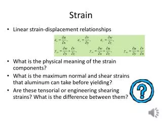
When strain gauges measure the changing dimensions of an object, they are measuring strain. Strain is the ratio of the change in dimension of an object to the original dimension Mechanical strain ε = ΔL / L When subject to strain, its resistance R changes, the fractional change in resistance ΔR/R being proportional to the mechanical strain i.e. Electrical strain ΔR/R= G . ΔL/L where G is the gauge factor (1.8 – 2.2) R varies between 50 Ω and 2KΩ
2 R1 R2 Vo 1 4 R3 R4 3 Vin Wheatstone Bridge • The four arms of the bridge circuit are formed by the resistance R1 to R4. • The corner points 1 and 4 are connected to the input voltage Vin • The corner points 2 and 3 are connected to the output voltage Vo.
Interpretation of results(Example 1) Meter reading
(Example 2) Meter reading
Strain Gages - review • Strain = Elongation / Original Length • Change in length = Change in electrical resistance • Electrical Resistance change is very small, too small to be accurately measured using ordinary voltmeters
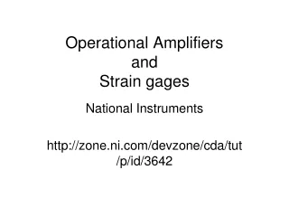
Converts a change in electrical resistance from a strain gage to a change in voltage Changes in strain are linearly related to a change in voltage output Voltage change is too small to be accurately measured and for this reason an amplifier is used Wheatstone Bridge