Download
1 / 48
480 likes | 585 Vues
SECTIONING OF A MACHINE COMPONENT BY ANY ONE SECTION PLA NE ,OUT OF THREE FOLLOWING MENTIONED SECTION PLANES. BY A VERTICAL SECTION PLANE (PARALLEL TO PRINCIPLE V.P.) Hence , The real or true shape of the section is observed in its F.V., known as SEC. F.V. - AB

E N D
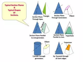
SECTIONING OF A MACHINE COMPONENT BY ANY ONE SECTION PLA NE ,OUT OF THREE FOLLOWING MENTIONED SECTION PLANES
BY A VERTICAL SECTION PLANE • (PARALLEL TO PRINCIPLE V.P.) • Hence , • The real or true shape of the section is observed in its F.V., known as SEC. F.V. - AB • Section plane will be seen as a cutting plane line (similar to center line ,thick at ends) with corresponding horizontal vision direction arrows at the center of thick ends in its T.V. & S.V.
(2)BY A HORIZONTAL SECTION PLANE • Hence, • The real or true shape of the section is observed in • its T.V., known as SEC. T.V. - AB • (b) The cutting or section plane will be observed as a • cutting plane line (similar to center line ,thick at • ends) with the corresponding vertically downward • vision direction arrows at the center of the thick • ends in its F.V. and in S.V.
(3) BY A SECTION PLANE , NORMAL TO BOTH H.P. AND V.P. (i.e. parallel to profile plane or side view plane) Hence, (a)The real or true shape of the section is observed in its S.V., known as SEC. L.H.S.V – AB or SEC. R.H.S.V - AB (b) The cutting or section plane will be observed as a cutting plane line (similar to center line , thick at ends) with the corresponding vertically downward vision direction arrows at the center of the thick ends in its F.V. and in T.V.
Figure shows isometric view of a machine component. Draw its • Front view, Top view & L.H.S View, using 3rd angle method of projections. • Sectional Front view, Top view & L.H.S.V., using 3rd angle method of projections. 60 B 40 30 15 10 30 50 15 5 R12.5 15 50 30 X A 50
Ortho. Views (No sectioning) 10 1. 30 60 30 40 15 25 5 50 50 X Top View 50 15 L.H.S.View Front View
B X A B It will be nearer to V.P. in 1st angle method & against the vertical plane in 3rd angle method. X Retained split of the machine parts A
(With sectioning) 10 A B 30 60 30 40 15 25 5 50 50 2. A B Top View A B Sectional Front View -AB L.H.S. View
Figure shows the pictorial view of a machine component. Draw its following views as per First angle method of projections 28 A (1) Front view from X direction. (2) Sectional top view-AA Ø20 Ø30 (3) L.H.S. View 60 A 20 7 14 120 20 28 X
Sketch shows the assumed cut model (retained part of the machine component / split against the observer) due to horizontal section plane passing through AB. 120 20 X 28
Ø20 Ø30, 7deep 20 A A A A 60 20 120 L.H.S.V. F.V. 28 14 Sectional T.V.
Figure shows the pictorial view of a machine components. Draw its following views, using 3rd angle method of projections. • Front view from arrow X • Top View • Sectional R.H.S.V - AB 30 10 B 60 20 40 R10 20 90 60 A X
Retained split, will be nearer to V.P. in 1st angle method & against the vertical plane in 3rd angle method. B No hatching in this area as not contained in the section plane Retained split of the machine parts A
A 30 60 90 20 20 40 T.V. A 80 SEC. R.H.S.V 20 F.V. A
SPECIAL SECIONS HALF SECTION
HALF SECTIONAL F.V.-AB HALF SECTIONAL LEFT S.V.-BC In half section the hidden line should be used only on unsectioned side of the view, provided that they are necessary for dimensioning or for clarity. B A C TOP VIEW
SPECIAL SECTIONS REMOVED & REVOLVED SECTIONS
REMOVED SECTION REVOLVED SECTION REMOVEDSECTION
NOTE:- (As per Previous I S 696 – 1972 Page 38) When the cutting plane passes (contains) the center line of such elements as, Shafts,bolts,nuts,rods,rivets,keys,pins, pulley arms, spokes, webs(ribs),screws,ball or roller bearings or similar shapes - no section lining or sectioning is needed for the objects , i.e. the hatching should be eliminated. (See the next demonstrating exercises following the above rule)
Vertical Collared Shaft (supported on webbed and drilled flange) in Conventional section in F.V., along with the T.V. Note:- As a rule, all the hidden lines should be omitted from a sectional view. The only exemption is where the hidden lines are absolutely Indispensable for clarification or for dimensioning. Actual or true projections are not preferred to draw
OFFSET SECTION:The path of the cutting plane is bent to pass through features not located in a straight line, i.e. it is offset to pass through both principle features of the object. Example is shown below in Ex. 1 & Ex. 2. R Section lines are to be staggered as shown at R B Ex. 1. B
P Q F.V (SECTION –AA) Off set sectioning Ex. 2. A A Section lines are to be staggered as shown at P,Q
Tap bolt(fastener) Partial (broken, local or Zonal) Section. pulley shaft See Ex. A,B & C Ex. A Shaft and pulley partly broken out to show internal fastening This is used to show only a desired features of the object . No cutting plane lines are necessary , shown by wavy line
SPECIAL SECTION A B SECTION IN TWO INTERSECTING PLANES SEC. F.V. - AB R.H.S.V.
SPECIAL SECTION Cross hatching of adjacent parts See at (1) & (2) (1)
SPECIAL SECTION Hatching more than two adjacent components at (2) C (hatched at 60 ) 45 B A hatched at 30 on D (2) D 45
A B F.V. SEC.T.V. Two vertical plates ,fastened by a horizontal rivet is shown in its F.V. & T.V., cut by horizontal section plane. Note the rivet is shown in section in T.V.
CONVENTIONAL REPRESENTATION OF CYLINDER IN WHICH CIRCULAR OR RECTANGULAR HOLE CUT IN ITS F.V. Note:- The actual shape of hole or slot may be understood from its side view. For circular hole ACTUAL PROJECTIONS For rectangular slot
AUXILARY SECTION A A SECTIONAA
AUXILIARY SECTION (as special section) It is the sectional view not in principal planes. it may be full, half ,broken out , removed or revolved.The section should be shown in its normal auxilary position and clearly identified with a cutting plane with letters
SUCCESSIVE SECTIONS (REMOVED TYPE) B C D A A D C B SECTION AA SECTION BB SECTION DD SECTION CC
SUCCESSIVE SECTIONS (REMOVED TYPE) B C D A A D C B
SECTION AA SECTION DD SECTION CC SECTION BB SUCCESSIVE SECTIONS (REMOVED TYPE)
(With sectioning) A B A B 2. A B Top View Sectional Front View -AB L.H.S. View
70 13 7 15 Ø30,2 HOLES 26 7 15 15 30 26 Ø30 45 R20
13 Ø30,2 HOLES
15 70 7 12 26 13 10 15 15 30 81 26 ø30 R20 L.H.S.V. SCECTIONAL F.V.-AA 0 70 10 65 TOP VIEW
SOLUTION` 14 70 14 8 A A A 30 14 R35 8 Approx.25 A Φ20 8 R35 30 Φ36 Φ20 Φ36 14 2 HOLES,Φ 14 100 65 14 34 65 14` 14 A 14 100 70 100 A X Aim:-Sketch-1, shows Isometric View of a machine part. Draw its following orthographic views using third angle method of projections, giving dimensions. (1) Sectional F.V.-AA (2) T.V. (3) L.H.S.V TOP VIEW SECTIONAL FRONT VIEW AA LEFT HAND SIDE VIEW Sketch-1 SCALE:- 1:1 SYMBOL OF PROJECTION METHOD, NOT SHOWN
SOLUTION` 14 70 14 8 A A A 14 R35 Approx.25 A 14 Φ20 8 R35 Φ36 Φ20 Φ36 2 HOLES,Φ 14 100 34 65 A 14 100 A X Aim:-Sketch-1, shows Isometric View of a machine part. Draw its following orthographic views using third angle method of projections, giving dimensions. (1) Sectional F.V.-AA (2) T.V. (3) L.H.S.V 30 TOP VIEW SECTIONAL FRONT VIEW AA LEFT HAND SIDE VIEW Hatch (section) lines, to be kept at 1 to 1.5 mm apart, at 45° normally, but depends on areas to be hatched. SCALE:- 1:1 SYMBOL OF PROJECTION METHOD, NOT SHOWN
60 40,DEPTH 24 50 30 14 70 10 48 14
Ø40 Ø64 24 50 30 10 140 14 48 14 70 TOP VIEW L.H.S.V FRONT VIEW