Download
1 / 27
270 likes | 277 Vues
ATLAS ID Upgrade. Scope R&D Plans for ATLAS Tracker First thoughts on Schedule and Cost. LHC SLHC s 14 TeV 14 TeV L 10 34 10 35

E N D
ATLAS ID Upgrade • Scope R&D Plans for ATLAS Tracker • First thoughts on Schedule and Cost
LHC SLHC s 14 TeV 14 TeV L 1034 1035 Bunch spacing t 25 ns 12.5 ns pp (inelastic) ~ 80 mb ~ 80 mb N. interactions/x-ing ~ 20 ~ 100 (N=L pp t) dNch/d per x-ing ~ 150 ~ 750 <ET> charge particles ~ 450 MeV ~ 450 MeV Track density 1 10 Pile-up noise in cal 1 ~3 Dose central region 1 10 Detectors: General Considerations
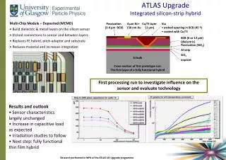
Inner Tracking • Assumption is that the inner tracker will need to be re-built using higher granularity detectors in a harder radiation environment in order to preserve the current pattern recognition, momentum resolution, b-tagging capability. • aRadiation increase by ~ 10. • a To keep Occupancy constant granularity has to increase by a factor 10. • Small Radius Region: Vertex detector (r < ~20cm) • aim for a pixels size factor ~ 5-8 smaller than today • (50x400 mm2g ~ 50 x ~ 50 mm2) gbenefit b-tagging, t-tagging • R&D: • Pixels Sensor Technologies • Super rad-hard electronics to achieve small pixel size
Inner Tracking • Intermediate Radius: ~20<r<~60 cm • Aim for cell sizes 10 times smaller than conventional Si strip • detectors. • benefit: momentum-resolution and pattern recognition • R&D: • Lower cost/channel compared to present Si strip detectors • Si macro-pixels of an area ~1mm2 : pads or shorter strips ? • Single sided two dimensional readout (new concepts) • Large Radius: ~60<r • Large area Si detectors. • Could use present day ‘radiation resistant’ strip technology, • or new single sided technology • R&D: • Similar to intermediate radius – less demanding except for cost.
Inner Tracking Engineering/Integration: Aim at a factor of ~10 more channels but with less material. This means that the System aspects have to be integrated and understood from the start. R&D: new light weight materials for stable structures. Power & Power distribution. Multiplexing of readout. cooling. alignment. installation and maintenance aspects. (replacement of existing infrastructure) Activation: 250 mSv/h – implications for access and maintenance Timescale : Need ~ 8-10 years from launch of R&D ~ 4-6 years of R&D and prototyping , ~4 years to build,
Simulation:Detector geometry, readout granularity. Support Structure:Integrated Support of the ID, “Mass less”. Cooling:Thermal management of the system. Si Detector:Technology, Contact with industry. Readout:Technology,Power, Connections. Module Layout:Technology, Integration at the module level. System Infrastructure:Cabling, Multiplexing, Optical Links: Power consideration,multiplexing, Rad hard. 9. Power Supplies: Location, distribution, Cabling. Radiation Hardness:Radiation hardness of ALL components. 11. Assembly/Installation:Assembly and installation above ground and in pitt. 12. System Tests:Validation of the performance at the system level. R&D Scope
Tracker configuration:Overall optimization of the tracker. Number of layers in the inner , middle and outer radius. Sensor geometry:For each layer determine the detector granularity, readout geometry. Optimal readout:Analog.vs. digital, speed of the readout. Data Compression:Study possible data compression schemes. Simulation
Simulation: detector geometry, readout granularity Space – Boundary Conditions TRT SCT Pixel
Conceptual design: beam pipe support Vertex detector support Intermediate Si tracker support Outer Layer Support Assembly Technology: Materials Optimal Configuration Assembly FEA Calculations Services/Cooling interface: Integration of the Support structure and the services/cooling. Interface to the Thermal Shield. 2. Support Structure
Conceptual Design Cooling capacity Cooling method Evaporative Cooling Binary ICE Operating temperature Pixels and SCT run at –70C Thermal enclosures Heat Shields and thermal divisions Cooling Control Prototype Cooling System 3. Thermal Management
Issues: Cost – Detector /Readout Connectivity Radiation hardness Optimal temperature operation Detector Technology: Inner Radius Candidate Technologies: 3D – readout Integrated readout and Pixel in one wafer Cryogenics detectors Middle and Outer Radius: 2D Single sided detectors “Macro pixel Detectors” Si Strips Wafer Size Wafer Size – aim to go to higher Wafers to reduce cost as well as number of detectors. Presently 6” are used should be able to go to 8” and possibly 12”. 4. Si Detector - I
Issues: Multiplexing Technology: ATLAS SCT readout used the DMILL process – will not be available to upgrade PIXEL has used IBM deep sub-micron need to investigate the limit of the radiation hardness of this process. New readout chip development: Tools 5. Readout
Issues: Module layout and interface to readout electronics. Interface to services. Production Cost. Industrial Solution vs. Assembly at inst. Technology: 6. Module Layout - I
Issues: Cable routing. Multiplexing. Production Cost. Industrial Solution. 7. Cabling/ Multiplexing/ Grounding.
Issues: Development of new fast optical Links – Power. New technology – Industrial solution. Production Cost. 8. Optical Links
Issues: Location of power supplies. Optimal Multiplexing of power and implication on Noise, Cable, cost etc. New readout technology moves toward low voltage, implication is that we will need very large currents unless we can “Ladder” the power. 9. Power Supplies
Issues: Testing of all components to new levels. 10. Radiation Hardness
Issues: Replacing present ID with new one – while the rest of the experiment stay in tact more or less. E.g: Cable routing when the Muon chambers are in place? Do we need to remove BIL, BIS Chambers? Max amount of cables services we can route? 11. Assembly /Installation
Issues: Ideas on multiplexing, power dist. Etc. all need to be confirm in a ‘realistic” condition. Cooling systems need to be tested and developed. Combine test of the whole system needs to be done to validate both the concept and the “system” aspects. ATLAS was (is) very weak on this point. 12. System Tests
ATLAS will start running in ’07 and for the first 5 years will operate with the present ID. After ~ 5 years the LHC Luminosity will be upgraded and a new and improved ID will be needed. Even if there is no Luminosity upgrade we expect that the ID will need to be upgraded. The time scale is: Formal proposal ’04 Identify Collaborators in the US and outside. R&D – “directed” Generic ’04-’09 Proposal for ATLAS Upgrade ’09-’10 Production of New ID Tracker ’10-’13 Installation of new ID Tracker ’14 Tracker Upgrade Schedule
The estimate is very preliminary and is based on the following assumptions: The active components of the tracker are all Si. The inner radius has upgraded Si Pixel detectors, followed by Si Strip detectors, in the outer radius we use single sided 2-D Si detectors. The estimate was done by scaling the cost of the ATLAS Si detector as well as information from CMS, and the CDF/D0 upgrade cost. In scaling the costs we had to make assumptions on how the main cost drivers will scale with the number of channels, the area and the expected time evolution. The R&D and final design will have to be driven by optimizing the cost to performance of the overall system. Tracking Cost estimate
Mechanics:The mechanics does not scale with the number of channels. One has to keep the services and the total weight to a minimum. The cost estimate assumes there is added complexity due to light weight: Si Detectors:Scale with the detector area. The optimization of the number of layers and exact location has not been finalized. The total amount of Si will be factor of ~ 5-10 greater than the present ATLAS detector. Possible cost reduction: Si detectors: Cost is driven largely by wafer size. Industry is moving toward larger wafers. Minimize the the amount of Si: by using advances in detector technology. For example single sided 2D readout can be used in the medium and larger radii where the segmentation needs are dominated by tracking accuracy rather than occupancy. Tracking Cost estimate
On detector read out electronics: The readout electronics cost is driven by the number of channels. Take advantage of the reduction in the feature size of the electronics. (ATLAS design used ATMEL/DMILL rad hard technology that has a conservative feature size of 1.2 Micron in the Strips. CMS and ATLAS pixels are using sub micron technology of 0.25 micron) Present industry standard is 0.18 moving toward 0.13 microns. Expect that by the time we go into production the standard feature size will be as low as 0.08 microns. Allowing for a substantial reduction in the power and space needed for the electronics and allowing for finer granularity without an increase in power and space needed. The reduction in power has important implication also on the cooling and services that will be needed. Tracking Cost estimate
Module integration: Module integration costs include costs of Hybrids and the components assembly. In the case of the Pixel detectors the cost of bump bonding Si is a significant part of the module integration. Significant cost reductions are possible assuming one of the integrated developments matures in time. They integrate the readout and the active detector on the same wafer eliminating the need for individual bonds. Cables & Data Links: Assumed a higher level of multiplexing compared to the present solutions. In particular the amount of power cables that need to be reduced for physics (reduced mass), space and cost reasons. Power Supplies: Power supplies will need to be optimized and serve a larger number of modules. This has implication on coherent noise and very detailed system integration will be needed to achieve this. Tracking Cost estimate
Cooling: (Additional)The needed cooling capacity will scale with the number of channels, but we have taken advantage of the lower power requirements of the lower feature size electronics. A large part of the external cooling can be reused. Off detector electronics: (Read out Drivers)We have to take advantage of advances and reduction in the cost of electronics. We assume that a factor of 10 more data 10 years from now will cost factor of ~ 1.5 more than present cost. The Tracker cost for one detector thus estimated to be between 150-180 M$. (assuming the full detector is built in the US) These numbers are only given as a rough estimate. We are not ready for an engineering estimate, which will have to be done after R&D has progressed and better optimization done. What should be the US part? Tracking Cost estimate
Tracker Upgrade is a complex technical problem. The R&D plan needs significant effort – in many areas. An ATLAS wide collaboration will need to be established for the execution of the project. U.S. should plan a significant role in the ATLAS Tracker upgrade. With ATLAS detector still not completed and installed. Preparations for Physics on going we need to find the right balance for this effort. Conclusions