Download
1 / 21
220 likes | 435 Vues
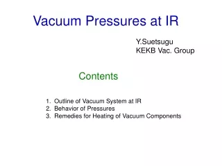
Vacuum Pressures at IR. Y.Suetsugu KEKB Vac. Group. Contents. Outline of Vacuum System at IR Behavior of Pressures Remedies for Heating of Vacuum Components. Vacuum System at IR.

E N D
Vacuum Pressures at IR Y.Suetsugu KEKB Vac. Group Contents • Outline of Vacuum System at IR • Behavior of Pressures • Remedies for Heating of Vacuum Components
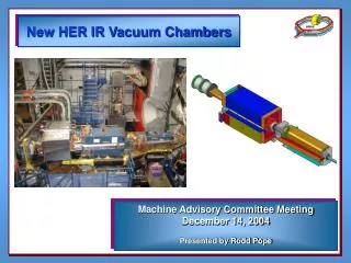
Vacuum System at IR • Here IR (Interaction region) means the straight section in ±~100 m from IP (Interaction Point), especially upstream side of each ring. • Material of beam duct: OFC (Oxygen Free Copper) for most part (both rings). Aluminum alloy for complicated chamber just near to IP. [Aluminum Alloy] [OFC]
Vacuum System at IR • Vacuum pump: Main pump = NEG (st707) : almost every 1 m (0.2 m3/s), Auxiliary pump = Ion pumps : almost every 10 m (0.2 m3/s). In average, about 0.7 m3/s/m just after an activation of NEG. NEG cartridge (arc section) NEG module (just near to IP)
Vacuum System at IR • Vacuum gauge = CCG (Cold Cathode Gauge) just above ion pumps (every ~10 m). A small dipole magnet (permanent magnet) is attached at the neck of gauge port to eliminate photoelectron effect. Without Manget CCG ~100 G
Vacuum System at IR • Location of Gauges and Pumps near to IP HER LER D01_H02 D02_H23 IP D01_H02A D01_H01A D02_H23A (D02_H24) [Inside of BELLE Solenoid] Integrated NEG Integrated NEG 0 10 m 5 m
Vacuum System at IR • HER Upstream Side (straight section, ~100 m) • Straight : No bending magnet • Gauges: every ~10 m D01_H01A D01_H03 D01_H02A D01_H04 D01_H05 IP GV GV D01_H06 D01_H7 D01_H8 GV BS D01_H10 D01_H09 D01_H11 HER
Vacuum System at IR • LER Upstream Side (straight section, ~100 m) • Local correction region: 13 bending magnets • Gauges: every ~10 m LER D02_L16 D02_L17 GV BS GV D02_L19 D02_L20 D02_L18 IP GV D02_L21 D02_L22 D02_H23A D02_L23 D02_L24
Behavior of Pressure • HER_1 Three days including several beam Injections. D01_H04 D01_H03 D01_H02A D01_H01A IP D01_H06 D01_H7 D01_H8 2x10⁻⁷ Pa Heat Source = Gate Valve P Big BG Source 0 0 1.4 A Ib
Behavior of Pressure • HER_2 Three days including several beam injections. Gate Valve D01_H7 D01_H8 Gate Valve D01_H06 D01_H09 Heat Source = HOM Absorber, Taper D01_H10 D01_H11 Heat Source = Stopper (~ Gate Valve)
Behavior of Pressure Three days including several beam aborts. • LER_1 ? (NEG?) D02_L20 D02_L18 D02_L19 IP D02_L21 D02_H23A D02_L23 Heat Source = Gate Valve D02_L22 D02_L24 3x10⁻⁷ Pa P Heating +NEG? Multipactoring? 0 0 2.0 A Ib
Behavior of Pressure Three days including several beam aborts. • LER_2 Heat Source = Taper Heat Source = Stopper D02_L16 D02_L17 D02_L15 Gate Valve Gate Valve D02_L19 D02_L20 D02_L18 ? (NEG?)
Present Status • The pressures near to IP is <1x10⁻⁷ Pa for HER and ~2x10⁻⁷ Pa for LER at the maximum operation current. • The pressures at upstream side of IP (IR) is almost less than 1x10⁻⁷ Pa,but affected by the heating of components, such as gate valves, stoppers, HOM absorbers and NEG(?). • The same harmful effect by heating can be seen widely in arc sections too. A major problem for further improvement of pressure.
Remedies to heating • Main reason of the heating is HOM. • Heating of Gate Valves, Stoppers and Bellows • Finger-type RF shield is not enough for high current • TE mode can easily coupled to modes outside • Tentative measure = Cooling from outside [Gate Valve] symptomatic therapy [Bellows]
Remedies to heating • Future (more essential) measure • Proposal of a New RF-shield structure • Comb-type RF-shield • 6 circular-type and 1 race-track-type has been installed in LER, and showed good results. • Application to gate valves are now planed and a test model will be installed in the ring this winter.
Remedies to heating • Heating of NEG • Gas desorption from heated NEG had been observed near collimators. • HOM (TE-mode) intruded through a grid into pump port. • Tentative measure = use a special gasket f = 6 mm t = 2 mm Cu Lead to heating of other components • HOM absorber were installed finally.
Remedies to heating • Heating by other HOM sources, such as collimators or tapers. • Install HOM absorber chamber • Example installed near collimators • HOM absorber = SiC SiC Slot Wing SiC Beam Chamber Require Space ! How about IR?
Summary • The pressures at upstream side of IP is almost less than 1x10⁻⁷ Pa, but also affected by the heating of components, such as gate valves, stoppers, tapers, NEG and HOM absorbers. • The problem had been solved accordingly so far. But, essential (drastic) remedies, such as employing new RF-shield or installing HOM absorbers, will be required for future high current operation. • Improvement of pumping speeds and cooling capacity are of course important.
Present Status • Typical Run(11/09/2004) Beam Current 1.2A x 1.6 A Lifetime 230, 180 min Ave. Pressure 10-7 Pa Luminosity ~1.1x1034cm-2/s Beam currents are usually limited by any problems in vacuum components
Present Status (If S = 0.3 m3/s/m) • Vacuum Aging (arc section, -2004/10/31) • DP/DI : 1x10⁻⁷ Pa/A • Photo-desorption coefficient,h : ~ 3x10⁻⁷ mole./photon • Effect of photoelectrons were eliminated by magnets. • HER seems to be effected by heating of components. [LER] [HER] DP/DI DP/DI Max. I Max. I [Pa/mA] [Pa/mA] PM PM [mA] [mA] (Corrected) [PM]:Set permanent magnets to every gauge port
Present Status Just near to GV! • Vacuum pressures in HER (~300 gauges) (ARES) (ARES) (SCC) (SCC)