Download
1 / 7
70 likes | 165 Vues
본 자료는 1997 SIA roadmap, 1997 OITDA roadmap,1999 MEL-ARI OPTO roadmap 등의 자료와 Stanford Prof. D. Miller 의 short course (Photonic-West 2002) 자료 , 그리고 , 개인적인 의견을 약간 가미하여 준비한 자료이다 . 가능한 한 객관적인 시각을 유지하기 위하여 technical data 위주로 작성되어 있다 .

E N D
본 자료는 1997 SIA roadmap, 1997 OITDA roadmap,1999 MEL-ARI OPTO roadmap 등의 자료와 Stanford Prof. D. Miller 의 short course (Photonic-West 2002) 자료,그리고, 개인적인 의견을 약간 가미하여 준비한 자료이다. 가능한 한 객관적인 시각을 유지하기 위하여 technical data 위주로작성되어 있다. • 언제 optics가 computer 내에서 주도적인 역할을 할 것인가? - 2007-2010 년 사이 • 그러한 근거를 결론적으로 요약해 본다면 다음과 같다. • IT 산업적 측면에서 보면, 2007-2010 사이에 electronic interconnection line의 속도가 CPU 처리속도에 비해 매우 떨어지는 시기에 optical processor가 요구될 것이고, • 프로세서에서의 화상처리 요구에 의해 1024x1024 image 처리를 위한 10G computing operation이 필요하고,-device 측면에서 보면, silicon-based CMOS IC와 integration된 광소자들의 개발시기도1024 I/Oarray크기로cost effective하게 개발될 것이고, • system 측면에서 보아도, 그때 정도면opticalmodule packaging및 integration이electronic system에 대해 경쟁력을가질 수 있지 않을까 하는 등의 근거에 바탕을 두었다. • 결론적으로 말한다면, processor 혹은 computer 전체가 all-optical system으로 이루어 지는 시기가 아니라, CPU, Memory 등 logic operation이 필요한 chip들과 power driver등은CMOS-based IC들을 그대로 쓰고, board-to-board level에서 시작하여chip-to-chip level 까지의 connection을 optical로 하는 optoelectronically interconnected system 이 이루어 지는 시기라 하는 것이 정확한 표현일 것이다. • 이는 마치all optical communication을 어디까지 이루어 진 것으로 정의하고 언제 될 것인가를 예측하는 경우와 유사하리라 생각된다. • 2001. 3. 13 송석호
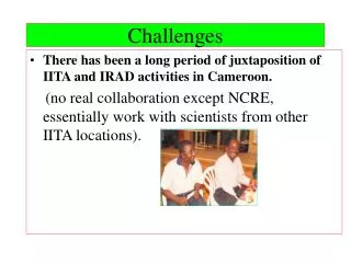
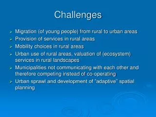
Challenges • Electronic interconnect system is far from death! • Cheap (2.3 cents/pin @2001, 1.5 cents/pin @2009) • Reliable and high performance • Optical interconnect system makes • Latency • Inadequate density of off-chip and intra chip connections • Poor processor-memory performance • High power comsumption • Absence of credible low-cost optoelectronics technology • High cost, cost, ………. • Optical system should be • Volume manufacturability (several millions) at low cost • Attached at wafer level by hybridization • Reliable, CAD integrated, hybridized, and cost effective!
Opportunities • Trends on electronic system (SIA 1997) show • 200 million transistors in logic IC chip @ 2006 • 20 km interconnection length in 140nm-based chip @2010 • 4000 I/O pins with 25 micron pitch in ASIC @2009 • 2.5 GHz speed in on-chip and off-chip @ 2009 • Electrical approach has physical limit on • connection-line length by RC and LC line response • bit rate = area/length^2 : (1Tb/s for 2cm wide, 5 micron thick, 4cm long lines) • Optical approach solves those problems and satisfies those trends in processor systems!
Core Technologies (1) • Optoelectronic devices • Photodetectors : p-i-n, avalanche, … • Light emitters : LEDs, edge emitting LD, surface emitting, • Optical amplifiers : SOA, Er-fiber • Light modulators : electroabsorption, electrorefraction • Device integration on Si-CMOS VLSI chip • Monolithic integration of III-V & II-VI on silicon • Hybrid integration : flip-chip & solder bonding • (128x128) GaAs modulator on CMOS – 1996 by Worchesky et al. • (16x16) VCSEL on CMOS – 1997 by Paananen et al. • Optical connectors • Fiber ribbon with VCSELs • 4*10Gbit/s 310m @850nm and 2.5Gbit/s 50km @1600nm • Polymer fibers and waveguides (100dB/km in CYTOP polymer)
Core Technologies (2) • Free-space optics devices and packaging • Chip-to-chip interconnect • Board-to-board interconnect • Slotted base-plate packaging • Optical MEMS • Planar optics • Microbridges, fiber image guide • Examples of waveguide & free-space interconnect system • Optical circuit board (2000) : polymer waveguide, 10 micron thick, 0.2dB/cm loss • Planar optics (2001) : fiber ribbon I/O with 6mm thick planar glass-board • Fiber image guide (2000) : space-variant connection • Multistage parallel switching system : 60,000 beams in parallel, 6 stages, 32x32 FET-SEEDs on CMOS (smart pixel) array
Electronics to Photonicsin Computing • Prototype of optically interconnected processor with electrical CPU and RAM CMOS chips can be realized between 2007-2010, because • Electrical line interconnects do not scale to keep up with transistor speed • On-chip global bandwidths may by > 30 Tb/s • CMOS can integrate smart network function ( ~10 Tb/s network router on a CMOS chip) • CMOS speed can match optical network speed (~10 GHz) • Optics join with mainstream CMOS (From David Miller, stanford, 2001) • VCSEL 1024 (32x32) @ 2002 4096 (64x64) @ 2007 • LED 4096 (64x64) @ 2002 16K (128x128) @ 2007 • 2D modulator 4096 (64x64) @ 2002 16K (128x128) @ 2007 • Detector 4096 (64x64) @ 2002 16K (128x128) @ 2007 • Waveguide 32~64 (2D) @ 2002 500~1000 (2D) @ 2007 • Free-space 4096 (64x64) @ 2002 16K (128x128) @ 2007 (From SIA and OIDA, 1997)
Parallel Optical Interconnection Optical Communication Protocol Bus Architecture VCSEL/PD Packaging Data Bus 2010 target of optoelectronic processor Single I/O channel bandwidth > 1 Gbit/s Number of parallel channels > 1000 Power consumption per channel <1 mW (From the roadmap of MEL-ARI OPTO, 1999) Near-term target • Interconnection by optics upto terabit memory with general-purpose CPU