Download

1 / 87
870 likes | 884 Vues
Automation Module. Engineering Foundation Course 2011. Contributors to the Course.

E N D
Automation Module Engineering Foundation Course 2011
Contributors to the Course Steven Laycock: Technology Leader for Process Control and Automation in Unilever Europe since 2003 and the Global Engineering Excellence Team. Joined Unilever (Leeds) in 1996, after working for an independent systems integrator. Stuart Dow: Systems Development Manager with Haden Freeman Ltd. (engineering design and consultancy company). 13 years as engineer & manager working on projects in a variety of industry sectors. Karam Rehani: Head of Instrumentation & Controls in Unilever India & AAMET since 1994. Joined Unilever (HLL) in 1981 & has worked at various locations manufacturing soaps, detergents, personal products & chemicals. Before joining Unilever, worked for 9 Yrs with Leading fertiliser co’s in India. Adhi Winata K : Instrumentation, Control, Automation & Electrical Manager in Unilever Indonesia. Joined Unilever in 2006. Before joining Unilever, worked with telecommunication company. Endress + Hauser : Live Product Demo Rockwell Automation : Live Product Demo Siemens : Totally Integrated Automation Concept (Presentation Content)
Objective What are we going to cover today • 3 key areas • - Understanding of the use of control systems • - Key knowledge necessary to manage an automation project • - Reasons to choose from the control options available
Agenda Section 1: Introduction to Control Building blocks – Measurement & Action Example Equipment (Endress & Hauser) Section 2: Building Blocks – Evaluation & Logic Pack Line Case Study : OMAC (Rockwell) Section 3: Automation Projects & Industry Standards Process Plant Case Study : Implementation of ISA S88 & ISA S95 (Rockwell) Section 4: Multiple Choice Questionnaire
Agenda Section 1: Introduction to Control Building blocks – Measurement & Action Example Equipment (Endress & Hauser) Section 2: Building Blocks – Evaluation & Logic Pack Line Case Study : OMAC (Rockwell) Section 3: Automation Projects & Industry Standards Process Plant Case Study : Implementation of ISA S88 & ISA S95 (Rockwell) Section 4: Multiple Choice Questionnaire
Reasons for Automation Quality : Better quality, fewer rejects Marketing:A marketing push may require increased production, re-branding, re-packaging or new formulations for example, or a requirement to search for new growth or markets Commercial: Higher output, lower utility costs, better yield, less labour It is to realize highest productivity enhancementsby intelligently connecting quality, speed, and cost and finding the optimal balance between all three
Automation Characteristics • Software for Controller and HMI programming : • STEP 7 (Siemens) • RSLogix 5000 (Allen-Bradley) • Safety for humans & machines : • Safety Interlock • Alarm Management • Safety Integrated Solutions (SIS) • IT Security in the network : • Restricted Access • Firewall • Encoding • VPN Network • Industrial capability equipment with highest robustness : • Industrial Type Hardware • Diagnostic functionalities that enable fast detection and correction of errors : • Maintenance Station • Engineering Station • Standard data transparency across all automation levels : • Communication Protocol • Logger / Historian • Report
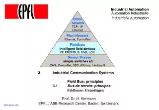
Automation System Components The Automation Pyramid ERP Enterprise Resource Planning System Basic functions of the business. Production Planning, Material Management MES Manufacturing Execution System Measure and control critical production activities. Equipment tracking, product genealogy, scheduling, KPI monitoring SCADA “Supervisory Control & Data Acquisition” System Interface to monitor & control the manufacturing plant HMI, Data Logger / Historian, Batch Management Control Level Monitor & control the manufacturing plant PLC - “Programmable Logic Controller”, PC Based Controller, Single / Multiple Loop PID (Proportional, Integral, Derivative) Controller Field Level Final executor of the manufacturing plant Sensors, Actuators, I/O Module, Hardware
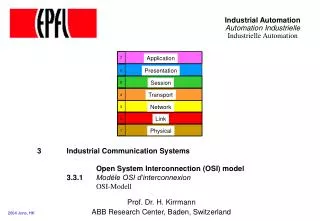
Automation System Components Response time and hierarchical level ERP(Enterprise Resource Planning) Planning Level MES (Manufacturing Execution System) Execution Level SCADA (Supervisory Control and Data Acquisition) Supervisory Level DCS (Distributed Control System) Control Level PLC (Programmable Logic Controller) ms seconds hours days weeks month years
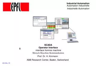
Automation System Components Application Example : Siemens Totally Integrated Automation Production Planning Material Management Production Order Management Detailed Production Scheduling Product Specification Management Production Operations Recording Data Logger Server HMI ServerBatch Server HMI ClientBatch Client Event Logger
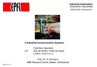
Automation System Components Real Plant Example : Skin Care Processing Plant Cikarang
Evaluate Action Information Basics How Do We Control? Monitor
Basics An Everyday Example We monitor the temperature. Is it too cold or too hot? If so we adjust the tap to correct. Wait for a bit (system dynamics) If temperature OK then have shower Else if temperature not OK adjust again (but with benefit of knowing impact of last adjustment) Go to ‘Wait for a bit’ and repeat.
Basics Control Loop
Instrumentation Engineering Foundation Course 2011
Agenda Section 1: Introduction to Control Building blocks – Measurement & Action Example Equipment (Endress & Hauser) Section 2: Building Blocks – Evaluation & Logic (Process & Packing Line) Pack Line Case Study : OMAC (Rockwell) Section 3: Automation Projects & Industry Standards Process Plant Case Study : Implementation of ISA S88 & ISA S95 (Rockwell) Section 4: Multiple Choice Questionnaire
Building Blocks:Measurement & Action • I. Monitoring & measurement • Process Instrumentation • Flow Measurement • Level Measurement • Temperature Measurement • Pressure Measurement • Analytical Measurement • Packing Line Sensors • II. Action • Process Instrumentation • Packing Line Actuators • III. Hardware Selection : Which to Pick
Building Blocks:Measurement & Action • I. Monitoring & measurement • Process Instrumentation • Flow Measurement • Level Measurement • Temperature Measurement • Pressure Measurement • Analytical Measurement • Packing Line Sensors • II. Action • Process Instrumentation • Packing Line Actuators • III. Hardware Selection : Which to Pick
Flow Measurement 1. Velocity • Measure the velocity flowrate • Example : • Magnetic • Turbine • Ultrasonics 2. Inferential • Determine flow by measuring some other physical property such as differential pressure, area meter, impact force, etc and then correlate it to flow • Example : • Differential Pressure (DP) : Orifice, Pitot Tube, Venturi • Area Meter : Rotameter • Impact Force : Target 3. Mass • Measure the mass flowrate • Example : • Coriolis Mass Flowmeter • Thermal Mass
Flow Measurement 1. Velocity Flow : Magnetic Flowmeter • A magnetic field at right angles to the flow stream is generated • Two opposing electrodes measure the voltage produced by the fluid moving
Flow Measurement 1. Velocity Flow : Magnetic Flowmeter Video Time !!!
Flow Measurement 1. Velocity Flow : Magnetic Flowmeter Advantages : • Capable of handling extremely low flow • Having very low pressure drop (no obstruction), minimize pumping cost • Suitable for most acids, bases, waters, and aquaeous solutions, because the lining materials are corrosion resistant • Widely used for slurry services • Can be used as bidirectional meters Limitations : • Work only with conductive fluids (can not measure pure substances, hydrocarbons, and gases) • Electrical installation care is essential (Proper Grounding) • Flow measurement inaccuracy due to fluids with magnetic properties (Liquid Sodium and its solutions)
Flow Measurement 1. Velocity Flow : Turbine/Paddlewheel A rotor (like a propeller) is supported by bearings to allow free rotation in the fluid flow. As the blades spin in the moving flow a pickup device counts the passing rotor blades and generates a frequency. As this frequency is proportional to the rate of flow and we know how much quantity each pulse represents we can calculate the volumetric flow.
Flow Measurement 1. Velocity Flow : Turbine/Paddlewheel Advantages • One of the most accurate flow meter (use for trading) • Having a fast response • Not sensitive to changes in fluid density (though at very low specific gravities, rangeability may be affected) Limitations • Not recommended for measuring steam • Sensitive to dirt • Can not be used for highly viscous fluids or for fluids with varying viscosity • Potential for being damaged by over-speeding (esp. during commissioning or start up)
Flow Measurement 2. Inferential Flow : dP Orifice Plate Orifice plate : a flat piece of metal with a hole bored in it. p+ p- A dP (differential pressure) is created across the plate. D d
Flow Measurement 2. Inferential Flow : dP Orifice Plate An instrument that can measure dP is connected by pipework (called impulse lines) to a tapping point on either side of the plate. The square root of the dP measured is proportional to the flow. (Normally accounted for in the electronics of the measuring instrument)
Flow Measurement 2. Inferential Flow : dP Orifice Plate Video Time !!!
Flow Measurement 2. Inferential Flow : dP Various Pitot Tube Venturi Tube Flow Nozzle Elbow Taps
Flow Measurement 2. Inferential Flow – dP Various
Flow Measurement 3. Mass Flow : Coriolis Effect Tube(s) are forced to oscillate at their natural frequencies perpendicular to the flow direction. The resulting Coriolis forces induce a twist movement in the tubes which is measured and is related to the mass flow.
Flow Measurement 3. Mass Flow : Coriolis Effect Video Time !!!
Flow Measurement 3. Mass Flow : Coriolis Effect Two most common types are the Straight Tube Curved Tube • Having a wider operating range, measures low flow more accurately • Available in larger sizes • Tends to be lower in cost • Having a higher operating temperature range • More sensitive to plant vibrations • Used mainly for multiphase fluids and for fluids that can coat or clog since the straight type can be easily cleaned • Having a low pressure loss • Reduces the probability of air and gas entrapment • Must be perfectly aligned with the pipe
Flow Measurement 3. Mass Flow : Coriolis Effect • Advantages : • Directly measures mass flow with high accuracy • High rangeability • Directly measure density • Highly independent of the flow profile and fluid properties (specific gravity and viscosity) • Can be used for many different applications, including corrosive fluids • Limitations : • High Price • Can not be used for liquids with any significant gas content • Not available for large pipelines • Not suitable for low pressure gases
Thermal Mass Flowmeter Target Weir & Flume Ultrasonic Flow Measurement Other Methods Vortex Shedding Variable Area / Rotameter
Flow Measurement Flowmeter Comparison Table
Flow Measurement Flowmeter Comparison Table (cont’d)
Building Blocks:Measurement & Action • I. Monitoring & measurement • Process Instrumentation • Flow Measurement • Level Measurement • Temperature Measurement • Pressure Measurement • Analytical Measurement • Packing Line Sensors • II. Action • Process Instrumentation • Packing Line Actuators • III. Hardware Selection : Which to Pick
Level Measurement 1. Pressure / Force • Pressure : Differential pressure, Diaphragm, Air bubblers • Buoyancy Force : Displacer 2. Position (height) of the surface • Wave : Radar, ultrasonic, Guided Radar (TDR) • Nuclear radiation • Electrical Properties : Capacitance, Conductance • Mechanical Contact : Floats, Tuning fork, Paddle wheel 3. Weight • Load Cells
Level Measurement Capacitance Pressure Pulse 6 GHz Radar Ultrasonic Guided Wave Radar TDR FMCWPulse 24 GHz Radar
Level Measurement 1. Pressure Static Head • Pressure/Static Head: (also known as hydrostatic) • Based on the height of the liquid head & the density of the liquid • - Accurate level calculation requires known & constant density • Advantages : • Have a wide range of measurement • Straightforward calibration • Limitations : • Affected by changes in liquid density (only for liquids with fixed SG) • Susceptible to dirt or scale entering the tubing Atmospheric Vessel Pressurized Vessel
Level Measurement 2. Position of Surface : Wave Wave is transmitted to target, reflected, and total transit time is determined Free Wave Guided Wave Free Wave Ultrasonic Guided Radar Radar
Level Measurement 2. Position of Surface : Wave
Level Measurement 2. Position of Surface : Electrical Properties Capacitive • Measures the changing electrical capacitance • Applicable for both conductive and nonconductive fluids • Provide both continuous and point measurement • The dielectric constant of the fluid must remain constant • Can not measure liquid interface Conductive • Electric current flows through the fluid, container wall and the probe which actuates a relay • Applicable for conductive fluids only • Provide only point measurement • Can provide differential level control (three-probe-type)
Level Measurement 2. Position of Surface : Nuclear Radiation • A radioactive source radiates through the vessel. The gamma quantum is seen by the radiation detector (such as a Geiger counter) and is transformed into a signal • Unaffected by temperature, pressure, and corrosion • Applied where other types of measurement cannot be used
Level Measurement 2. Position of Surface : Mechanical Contact Tuning Fork (Vibration) • Keeping the probe vibrate in its natural frequency • Relay triggered when process material in the tank reaches the vibrating elements and damps out the vibration • Applicable for both liquid and solid material Rotating Paddle Switch Float • Applicable for liquid material • Applicable for both point and continuous measurement • Small synchronized motor keeps the paddle in motion at very low speed • When level raised to the paddle, it is stopped • Applicable for solid material
Level Measurement 3. Load Cells The strain gauge (either foil or semiconductor) measures the stress which is introduced into a metal element, both compression & tension A bending beam type designuses strain gauges to monitor the stress in the sensing elementwhen subjected to a bending force.
Level Measurement 3. Load Cells Type
Level Measurement 3. Load Cells Comparison Table