Download
1 / 28
300 likes | 632 Vues
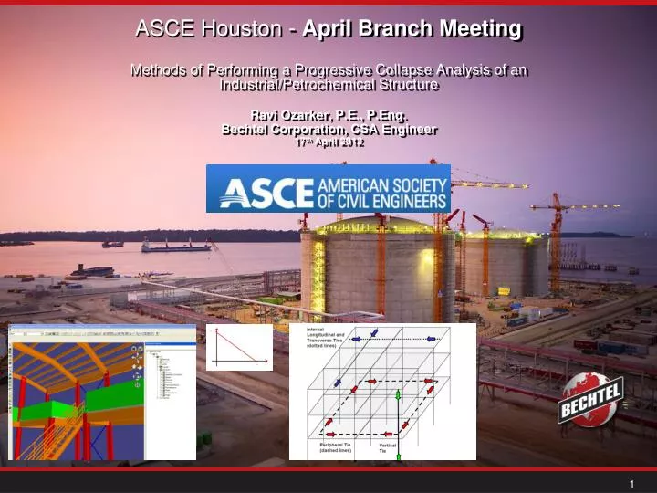
ASCE Houston - April Branch Meeting Methods of Performing a Progressive Collapse Analysis of an Industrial/Petrochemical Structure. Ravi Ozarker, P.E., P.Eng. Bechtel Corporation, CSA Engineer 17 th April 2012. Presenter. Ravi Ozarker, P.E., P.Eng.

E N D
ASCE Houston - April Branch Meeting Methods of Performing a Progressive Collapse Analysis of an Industrial/Petrochemical Structure Ravi Ozarker, P.E., P.Eng. Bechtel Corporation, CSA Engineer 17th April 2012
Presenter • Ravi Ozarker, P.E., P.Eng. • Bechtel Corporation, Senior Structural Engineer • rozarker@bechtel.com • (713) 235-6617
References • Ref. UFC 4-023-03 - Design of Buildings to Resist Progressive Collapse • Ref. ASCE 7-10 - Minimum Design Loads of Buildings and Other Structures • Ref. ASCE - Design of Blast-Resistant Buildings in Petrochemical Facilities • ASCE 41-06 - Seismic Rehabilitation of Existing Buildings • Wikipedia & Bechtel Images
Why is Progressive Collapse Analysis is Needed This Unified Facilities Criteria (UFC) provides the design requirements necessary to: • reduce the potential of progressive collapse for new and existing facilities that experience localized structural damage through normally unforeseeable events. • This UFC incorporates a prudent, effective, and uniform level of resistance to progressive collapse without expensive or radical changes to typical design practice.
What is Progressive Collapse Analysis? Progressive collapse is defined in the commentary of the American Society of Civil Engineers Standard 7 Minimum Design Loads for Buildings and Other Structures (ASCE 7) as “the spread of an initial local failure from element to element, eventually resulting in the collapse of an entire structure or a disproportionately large part of it.”
What is Progressive Collapse Analysis? Progressive collapse is a relatively rare event, in the United States and other Western nations, as it requires both an abnormal loading to initiate the local damage and a structure that lacks adequate continuity, ductility, and redundancy to resist the spread of damage. However, significant casualties can result when collapse occurs. This is illustrated by the April 19, 1995 bombing of the Alfred P. Murrah building in Oklahoma City, in which the majority of the 168 fatalities were due to the partial collapse of the structure and not to direct blast effects.
Causes of Collapse • Relatively rare but when they occur, consequences can be severe. • Blast (e.g. 1989 collapse of a control building Pasadena, TX during maintenance of a polyethylene unit. 23 fatalities and 120 injured). • Blast (e.g. 2005 destruction of trailers used as temporary office during restart of an isomerization unit. • Pressure vessel explosions • Vapor cloud explosions • Dust explosions
Design Approach? Two general approaches for reducing the possibility of progressive collapse: • Direct Design, and; • Indirect Design.
Direct Design Direct Design approaches include "explicit consideration of resistance to progressive collapse during the design process…" These include: • The Alternate Path (AP) method, which requires that the structure be capable of bridging over a missing structural element, with the resulting extent of damage being localized, and • The Specific Local Resistance (SLR) method, which requires that the building, or parts of the building, provide sufficient strength to resist a specific load or threat.
Indirect Design Approach With Indirect Design, resistance to progressive collapse is considered implicitly "through the provision of minimum levels of strength, continuity and ductility". The commentary in ASCE 7-02 goes on to present general design guidelines and suggestions for improving structural integrity. These include: • good plan layout, • integrated system of ties, • returns on walls, • changing span directions of floor slabs, • load-bearing interior partitions, • catenary action of the floor slab, • beam action of the walls, • redundant structural systems, • ductile detailing, • additional reinforcement for blast and load reversal, if the designer must consider explosive loads, and • compartmentalized construction. However, no quantitative requirements for either direct or indirect design to resist progressive collapse are provided in ASCE.
Design Procedures The progressive collapse design requirements employ three design/analysis approaches: • Tie Forces (TF) - The first level of progressive collapse design employs Tie Forces • Alternate Path (AP) - The second level employs the Alternate Path method, in which the structural mode is "flexural", as the building must bridge across a removed element, and • Enhanced Local Resistance (ELR).
Tie Forces In the Tie Force approach, the building is mechanically tied together, enhancing continuity, ductility, and development of alternate load paths. There are three horizontal ties that must be provided: longitudinal, transverse, and peripheral. Use to determine the required tie strengths: wF = 1.2D + 0.5L • Where wF= Floor Load (lb/ft2 or kN/m2) • D = Dead Load (lb/ft2 or kN/m2) • L = Live Load (lb/ft2 or kN/m2)
Tie Strength • Spacing must not be greater than 0.2 LT, or 0.2 LL where LT and LL are the greater of the distances between the centers of the columns, frames, or walls supporting any two adjacent floor spaces in the transverse and longitudinal directions, respectively. • The required tie strength Fi (lb/ft or kN/m) in the longitudinal or transverse direction is • Fi = 3 wF L1 Equation (3-3) • Where wF = Floor load, determined per Section 3-1.2, in • (lb/ft2 or kN/m2) • L1 = Greater of the distances between the centers of the columns, frames, or walls supporting any two adjacent floor spaces in the direction under consideration (ft or m)
Alternate Path Method The Alternate Path method is used in two situations: • for Option 1 of Occupancy Category II and for Occupancy Category IV, when a vertical structural element cannot provide the required tie strength, the designer may use the AP method to determine if the structure can bridge over the deficient element after it has been notionally removed, and • for Occupancy Category II Option 2, Occupancy Category III, and Occupancy Category IV, the AP method must be applied for the removal of specific vertical load-bearing elements which are prescribed in Section 3-2.9.
Analysis Procedures Three analysis procedures are employed: • Linear Static (LSP) If there are no structural irregularities as defined in Section 3-2.11.1.1, a linear static procedure may be performed and it is not necessary to calculate the DCRs defined in Section 3-2.11.1.2. If the structure is irregular, a linear static procedure may be performed if all of the component DCRs determined in the Section 3-2.11.1.1 are less than or equal to 2.0. If the structure is irregular and one or more of the DCRs exceed 2.0, then a linear static procedure cannot be used. • Nonlinear Static (NSP), and; There are no DCR or geometric irregularity limitations on the use of the NSP. • Nonlinear Dynamic (NDP). There are no DCR or geometric irregularity limitations on the use of the NDP.
Increased Gravity Loads for Floor Areas Above Removed Column or Wall GLF = Increased gravity loads for force-controlled actions for Linear Static analysis D = Dead load including façade loads (lb/ft2 or kN/m2) L = Live load including live load reduction per ASCE 7 (lb/ft2 or kN/m2) S = Snow load (lb/ft2 or kN/m2) ΩLF = Load increase factor for calculating force- controlled actions for Linear Static analysis; use appropriate value for framed or load-bearing wall structures;
Steel LNG Plant Structures • Material properties for structural steel • Strength reduction factor φ for structural steel • Tie force requirements for steel • Columns under high axial load (P/PCL > 0.5) shall be considered force-controlled, with the considered loads (P and M) equal to the maximum loads from the analysis
Blast Loads • ASCE Guide – Design of Blast Resistant Buildings in Petrochemical Facilities • Blast loads cannot be accurately predicted • Blast pressure vs. time curves are always assumed to be linear • P-I Diagrams (Pressure – Impulse Diagrams) • Numerical Integration (Time – History Method) • Non Linear FEA • Geometric Non Linear FEA
Simple Blast Load Calculation • Pso = Peak side on overpressure • Pr= Reflected pressure = Cr * Pso • Cr = ( 2+0.05 Pso) (psi) • Io = 0.5 Pso td • U=1130(1+0.058PSO)0.5 • Dynamic (Blast Wind) Pressure qo = 2.5 Pso 2/(7P0+Pso) = 0.022 (Ps0)2 • Pr decays to Ps = stagnation pressure Ps in the clearing time tc • Ps = Pso + Cd q0 • Tc = 3S/U • Iw = 0.5(Pr – Ps)tc_0.5Ps td • Te = 2Iw/Pr
Questions? Thank you for attending!