Download
1 / 72
740 likes | 1.12k Vues
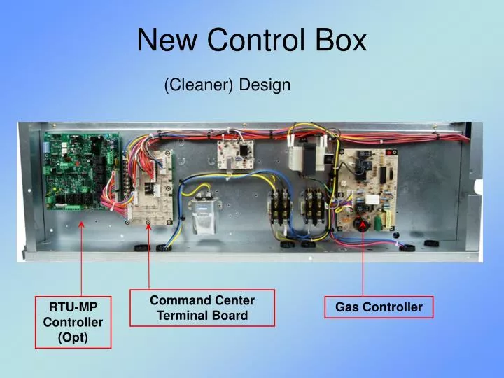
New Control Box. (Cleaner) Design. Command Center Terminal Board. RTU-MP Controller (Opt). Gas Controller. Controls: Cooling. High Pressure Switch Low Pressure Switch Indoor Fan Motor Overloads: Linebreak Thermik (pilot-circuit) External circuit-breaker. Controls: Cooling.

E N D
New Control Box (Cleaner) Design Command Center Terminal Board RTU-MP Controller (Opt) Gas Controller
Controls: Cooling • High Pressure Switch • Low Pressure Switch • Indoor Fan Motor Overloads: • Linebreak • Thermik (pilot-circuit) • External circuit-breaker
Controls: Cooling Control Transformer • 75 va • 3.2-A circuit breaker on transformer housing CLO -- Accy or FIOP
IGC Inputs Flame Sensor Hall Effect W1 Demand Speed Sensor Rollout Switch 24-v Limit Switch IGC Outputs Diagnostic LED Inducer Motor (CM) Indoor Blower (BM) IFO signal Gas Valve Sparker Controls: HeatingIntegrated Gas Controller (IGC)
Hall Effect Ref: Honeywell
Hall Effect:Pulse Output Signal Speed Sensor Logic Criteria Speed > 2400 RPM: Inducer Motor OK Speed < 2000 RPM: Combustion Terminated
IGC Error Codes:From NSMM 2003 (SPP PPT) in HVACPartners • Fault 2 – Limit Switch Open • If limit opens: • Gas valve and ignitor will be disable • Indoor blower will immediately energized. • Inducer shall remain energized • The indoor blower will turn off after the fan off delay if “W” goes away. • If limit closes again the fault will clear. If you still have “W”, the gas valve still open and re-igniton will occur.
IGC Service Reference Material • NSMM 2003 SPP PPT IGC Alarms • Technical Base / Hall Effect • Service Training GT54-01
New PN: HK32EA005 Thermostat demands for 1 or 2 stage Cooling 2 stage Heating Emergency Heating Defrost Control in Heating Mode Based on RES HK32EA003 Heat Pump Defrost Board
Controls: Heat Pump • HPS High Pressure Switch • Opens 660PSI. Close 505PSI • LPS Low Pressure Switch (A/C’s) • Opens 54PSI. Close 117PSI • Liquid Line Loss-of-Charge (HP’s) • Opens 27PSI. Close 44PSI • Freeze Protection Thermostat (FPS) • Opens 30F. Close 45F • Connects to new defrost board
Reversing Valve Operation • No O or B signal required • Energized in Cooling • Reversing Valve does not shift mode in Off cycle (No Dump)
Heat Pump Compressor Seq Cooling Stage 1: Reversing Valve 1 + Compressor Cooling Stage 2: (2-comp models only) Rev Valves 1+2 + Compressors 1+2 Heating Stage 1: Compressor(s), No Reversing Valve
Heat Pump Electric Heat Heating Stage 2 Concurrent with compressor(s) Emergency Heat Electric Heat WITHOUT compressors Defrost Tempering
Heat Pump Defrost Time-Temperature Sequence 1. Heat Run Time (30,60,90 or 120 mins) Factory 60 mins 2. Initiate if tube temperature (DFT) low 3. Terminate when tube temperature (DFT) rises or defrost run period reaches 10 min HH18SA261DFT Settings: Open: 30F Close: 80F
Defrost Speed-Up • JMP17-JMP18 (flat/slot screwdriver) • 1-5 secs: Speed-Up (0.1 sec/min) • 5-20 secs: Forced Defrost Run to normal termination or 30 secs minimum
Controls: Electric Heat Accessory installation 1 or 2 stages Fan housing limit switch (pilot, manual) Element line-break (or secondary contactor) Heater control contactor(s)
Electric Heat: Single-Point Box • Required with all electric heater installations • Splice box with cover • Power terminal block • Tap conductors • If FLA > 48-A: Fuse blocks and 60-A fuses
SERVICE MANUAL CONTROLS TERMINAL BOARD CONVENIENCE OUTLETS SMOKE DETECTORS
Installation InstructionsandService Manuals (SM) The complete unit installation procedure (rig and position through start-up) will require reference to two (or more) technical manuals. Mechanical Installation: SI (II) Configure/Start-up/Troubleshoot: SM
Specific Topic Tech Support Smoke Detectors: Application Tip Cat# HKRNKA-1XA (integration with building alarm systems) PremierLink: Form 33CS-58SI (configuration, t-s) RTU-MP: Form 48-50H-T-2T (configuration, t-s) RTU-MP 3rd Party Integration Guide
Controls Terminal Board aka Light Commercial Terminal Board (LCTB) Command Center Terminal Board Carrier PN HK50AA049 UTEC PN CEPL130904-01 Array of terminal strips, housings and QCs Contains NO LOGIC, no software
Controls Terminal Board Gas Controller Provides: - Clean connection points - Insures positive connections - Visual aid Phase Monitor OR Fire / Remote Shutdown OR Smoke Alarm LPS HPS
Controls Terminal Board 11 terminal strips: J1-J2: Screw terminals (thermostat wires) 0.046-in square pin 18 quick-connect terminals
CTB: Jumpers JMP7 JMP6 JMP5 • JMP1 Phase Monitor • JMP2 Occupancy Control • JMP3 Smoke Detector Shutdown • JMP4 Remote Shutdown • JMP5, 6, 7 Heat Pump / Reheat JMP1 JMP4 JMP3 JMP2
2010 FIOPs • Convenience Outlets • Smoke Detectors • CO2 Sensor (new)
Convenience Outlets • Non-Powered • Unit-Powered • Neither is connected as delivered • Hinged cover shipped loose (in control box)
Non-Powered: Duplex GFCI Weatherproof box Hinged cover Powered: Duplex GFCI Weatherproof box Transformer 15-A fuse/switch Hinged cover Convenience Outlets
Non-Powered CO • Provide a separate 115-v 15-A power supply and circuit disconnect from the building • Connect to the duplex outlet in the unit’s splice box • Install the weatherproof hinged cover
Powered CO • Check local codes to determine if connecting the convenience outlet transformer to the LINE side of the unit disconnect is acceptable. • If acceptable: Connect primary leads at the power transformer together as required for unit line voltage and connect to unit disconnect’s line side terminals. • If not acceptable: Connect primary leads at the power transformer together as required for unit line voltage and connect to unit disconnect’s load side terminals. • Install the weatherproof hinged cover.
Smoke Detector FIOPs • Supply Air (on supply fan housing) • Return Air w/o Economizer • Return Air with Economizer • Combine S/A and R/A R/A Smoke Detector is for VERTICAL only “Some assembly required”
Smoke Detector Hardware • Controller Module (one per unit) • Sensor Module (one or two required) • R/A application: Sensor tube