Download
1 / 35
390 likes | 609 Vues
Heat Exchangers Design and Construction. By kamal Nashar. Introduction:. Shell and tube heat exchangers are one of the most common equipment found in all plants. How it works?. What are they used for?. Classification according to service. Heat Exchanger.

E N D
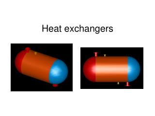
Heat Exchangers Design and Construction By kamal Nashar
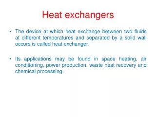
Introduction: • Shell and tube heat exchangers are one of the most common equipment found in all plants • How it works?
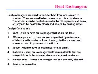
What are they used for? • Classification according to service . • Heat Exchanger Both sides single phase and process stream • Cooler One stream process fluid and the other cooling water or air • Heater One stream process fluid and heating utility as steam • Condenser One stream condensing vapor and the other cooling water or air • Reboiler One stream bottom stream from a distillation column and the other a hot utility or process stream
Design codes: • Code Is recommended method of doing something ASME BPV – TEMA • Standard is the degree of excellence required • API 660-ASME B16.5–ASME B36.10M–ASME B36.19-ASME B16.9–ASME B16.11 • Specifications • Is a detailed description of construction, materials,… etc • Contractor or Owner specifications
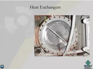
Main Components 1- Channel Cover 8- Shell 2- Channel 9- Baffles 3- Channel Flange 10- Floating Head backing Device 4- Pass Partition 11- Floating Tubesheet 5- Stationary Tubesheet 12- Floating Head 6- Shell Flange 13- Floating Head Flange 7- Tube 14 –Shell Cover
TEMA Heat Exchanger • Front Head Type A - Type B - Type C - Type
TEMA Heat Exchanger • Shell Type E - Type F - Type J - Type K - Type
TEMA Heat Exchanger • Rear End Head Types M - Type S - Type T - Type Fixed Tubesheet Floating Head Pull-Through Floating Head
Classification: • U-Tube Heat Exchanger • Fixed Tubesheet Heat Exchanger • Floating Tubesheet Heat exchanger
Example AES
Example AKT
Heat Exchangers Mechanical Design • Terminology • Design data • Material selection • Codes overview • Sample calculations • Hydrostatic test • Sample drawing
Terminology • ASME • TEMA • API • MAWP • MDMT • PWHT • NPS – DN – NB – NPT • Sch - BWG
Design Data • Heat Exchanger Data Sheet : • TEMA type • Design pressure • Design temperature • Dimensions / passes • Tubes ( dimensions, pattern) • Nozzles & Connections • Baffles (No. & Type)
Strength • A – Yield Strength B A C • B – Tensile Strength • C – Rupture point
Strength • Creep Strength a slow plastic strain increased by time and temperature (time and temperature dependant) for stressed materials • Fatigue Strength The term “fatigue” refers to the situation where a specimen breaks under a load that it has previously withstood for a length of time • Toughness The materials capacity to absorb energy, which, is dependant upon strength as well as ductility
ASME code Overview Sec.I Power Boilers Sec.II Materials Sec.III Nuclear Fuel Containers ASME BPV code Sec.IV Heating Boilers Sec. V Non Destructive Examination Sec. VI Operation of heating boilers Sec. VII Operation of power boilers Sec. VIII Pressure vessels Sec. IX Welding and Brazing Sec. X Fiber-Reinforced plastic PV Sec. XI Inspection of nuclear power plant Sec. XII Transport tanks
ASME code overview • Sec. II: Materials • Part A : Ferrous material specifications • Part B : Non-Ferrous material specifications • Part C : Specifications of welding rods, electrodes and filler metals • Part D : Properties • Sec. VIII: Rules of construction of pressure vessels • Division 1 : 3 Subsections + mandatory Annex + non mandatory Annex • Division 2: Alternative rules • Division 3 : Alternative rules of high pressure
TEMA code overview • TEMA classes: • Class R: Generally severe requirements for petroleum and related processing applications • Class C: Generally moderate requirements of commercial and general processing applications • Class B: Chemical Process service • TEMA subsections • 10 subsection
Sample Calculations • Shell thickness calculations under Internal Pressure: PR . t = + CA + UT SE – 0.6 P • t : Min. Required Shell Thickness • P : Design Pressure of Shell Side • S: Max. Allowable Stress of Shell Material • R: Shell Inside Radius (corroded conditions) • E : Joint Efficiency • CA: Corrosion Allowance • UT: Under Tolerance (if applicable)
Sample Calculations • Channel thickness calculations under Internal Pressure: PR . t = + CA + UT SE – 0.6 P • t : Min. Required Channel Thickness • P : Design Pressure of Tube Side • S: Max. Allowable Stress of Channel Material • R: Channel Inside Radius (corroded conditions) • E : Joint Efficiency • CA: Corrosion Allowance • UT: Under Tolerance (if applicable)
Sample Calculations • Body Flanges:
Sample Calculations • Body Flanges: • Trial and error calculations • Gasket seating conditions • Operating conditions • No. of bolts and size • Bolt circle diameter • Inside and outside diameters • Check min. and max. bolt spacing • Detailed analysis of the flange • Forces calculations • Moment calculations • Stresses calculations
Sample Calculations • Precautions in body flanges design and installations: • Pairs of flanges • Bolt holes shall straddle center line • Corrosion Allowance • Cladding • Bolts shall be multiple of 4 • Bolting shall be allowed to be removed from either side • Calculated thickness not include the RF
Sample Calculations • Nozzles and standard flanges: • Flange Rating (ASME B16.5) • Area replacement calculations • Nozzle neck thickness calculations • Impingement protection Sample
Sample Calculations • Tubesheet: • Tubesheet is the principal barrier between shell side and tube side • Made from around flat piece of metal with holes drilled for the tubes • Tubes shall be uniformly distributed • Tubesheet thickness shall be designed for both sides • Tubesheet shall be designed for bending stresses and shear stresses • Corrosion allowance
Sample Calculations • Tubesheet: • Tubesheet thickness for bending T: Effective tubesheet thickness S: Allowable stress P: Design pressure corrected for vacuum if applicable at the other side η: Ligament efficiency For Square pattern For Triangular pattern G: Gasket effective diameter F: Factor
Sample Calculations • Tubesheet: • Tubesheet thickness for Shear: T: Effective tubesheet thickness DL: Effective diameter of the tube center parameter DL=4A/C C: Perimeter of the tube layout A: Total area enclosed by the Perimeter C P: Design pressure S: Allowable stress do: Outside tube diameter
Tube-to-Tubesheet joint • Expanded • Strength welded • Seal welded
Hydrostatic Test • Test pressure : 1.3 X MAWP • Test Procedure • Gasket change
Sample drawing • Construction drawing is the design output Sample drawing 1 Sample drawing 2
Thank You Kamal Nashar kamal146@hotmail.com