Download
1 / 20
220 likes | 374 Vues
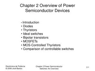
Overview of Power Semiconductor Switches. Presently available power semiconductor switches can be divided into three groups according to their degree of controllability: Diodes : ON and OFF states controlled by power circuits

E N D
Overview of Power Semiconductor Switches Presently available power semiconductor switches can be divided into three groups according to their degree of controllability: • Diodes:ON and OFF states controlled by power circuits • Thyristors:latched on by a control signal but turned OFF by the power circuit • Controllable switches:turned ON and OFF by control signals
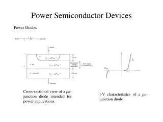
Diodes • On and off states controlled by the power circuit • Forward biased – conduction • Reverse biased – small leakage current flow until break down voltage reached
Thyristors • Semi-controlled device • Latches ON by a gate-current pulse if forward biased • Turns-off if current tries to reverse
Thyristor in a Simple Circuit • For successful turn-off, reverse voltage required
Generic Switch Symbol • Idealized switch symbol • When on, current can flow only in the direction of the arrow • Instantaneous switching from one state to the other • Conduct large current with zero voltage drop in on-state • Block large forward and reverse voltages with zero current flow when off • Infinite voltage and current handling capabilities
Bipolar Junction Transistors (BJT) • BJT is a current-controlled device • A sufficiently large base current will turn the device ON • Base current must be supplied continuously to keep it in the ON state • Used commonly in the past • Now used in specific applications, replaced by MOSFETs and IGBTs
Various Configurations of BJTs • dc gain is in the order of 5-10 of one BJT • To achieve larger current gain, these devices are sometimes connected in the above configurations.
MOSFETs • MOSFET is a voltage-controlled device • Easy to control by the gate – continuous application of vGS required to keep the device in the ON state • Faster switching speed (in the nanosecond range) than BJTs • Switching loss is lower compared to BJTs
Gate-Turn-Off Thyristors (GTO) • GTO as an ON/OFF switch • Once forward biased GTO can be turned ON by a gate pulse • GTO will stay ON • However, can be turned off by applying a negative gate-cathode voltage • Used at very high power levels • Require elaborate gate control circuitry
IGBT • High impedance gate – requires small amount of energy to switch the device • Current rating: ~1700 A • Voltage rating: 2~3 kV
Steady State in Power Electronics • Voltage produced by an inverter in an ac motor drive • Often line currents drawn from the utility by the power electronic circuits are highly distorted as shown in b
Inductor Voltage and Current in Steady State In steady-state, the average inductor voltage (over one time period) must be zero.
Capacitor Voltage and Current in Steady State In steady-state, the average capacitor current (over one time period) must be zero.