Download
1 / 52
530 likes | 621 Vues
Physical Layer: Data and Signals. 01204325: Data Communication and Computer Networks. Asst. Prof. Chaiporn Jaikaeo, Ph.D. chaiporn.j@ku.ac.th http://www.cpe.ku.ac.th/~cpj Computer Engineering Department Kasetsart University, Bangkok, Thailand. Outline. Analog and digital data/signals

E N D
Physical Layer: Data and Signals 01204325: Data Communication and Computer Networks Asst. Prof. Chaiporn Jaikaeo, Ph.D. chaiporn.j@ku.ac.th http://www.cpe.ku.ac.th/~cpj Computer Engineering Department Kasetsart University, Bangkok, Thailand
Outline • Analog and digital data/signals • Time and frequency domain views of signals • Bandwidth and bit rate • Transmitting digital signals as analog • Theoretical data rate • Signal impairment
Analog vs. Digital Data • Analog data • Data take on continuous values • E.g., human voice, temperature reading • Digital data • Data take on discrete values • E.g., text, integers
value time value time Analog vs. Digital Signals • Analog signals • have an infinite number of values in a range • Digital signals • Have a limited number of values To be transmitted, data must be transformed to electromagnetic signals
Analog Data Analog Signal Telephone Digital Data Analog Signal Modem Analog Data Digital Signal Codec Digital Data Digital Signal Digitaltransmitter Data and Signals
value period time Periodic Signals • A periodic signal completes a pattern within a timeframe, called a period • A signal x(t) is periodic if and only if x(t) = x(t+T) - < t <
signal strength periodT = 1/f peakamplitude time Sine Waves • Simplest form of periodic signal • General form: x(t) =A×sin(2ft + ) phase / phase shift
A = 1, f = 1, = 0 A = 2, f = 1, = 0 A = 1, f = 2, = 0 A = 1, f = 1, = /4 Varying Sine Waves
Time vs. Frequency Domains • Consider the signal + = Demo: sine.py
signal strength signal strength 1 1 0 0 2 4 2 4 time frequency -1 -1 Time vs. Frequency Domains Time Domain Representation plots amplitude as a function of time Frequency Domain Representation plots each sine wave’s peak amplitude against its frequency Demo: Equalizer
Joseph Fourier(1768-1830) + + + + … Fourier Analysis • Any periodic signal can be represented as a sum of sinusoids • known as a Fourier Series • E.g., a square wave: =
Fourier Analysis • Every periodic signal consists of • DC component • AC components • Fundamental frequency (f0) • Harmonics (multiples of f0) fundamentalfrequency 3rd harmonic 5th harmonic … DC component AC components
Note: cn are complex j = -1 eix = cos x + jsin x Fourier Series: Representations • Amplitude-phase form • Sine-cosine form • Complex exponential form (Euler formula) Demo: Falstad
... 0 0 3f0 5f0 7f0 9f0 11f0 f0 Frequency Spectrum • Frequency domain representation shows the frequency spectrum of a signal • E.g., square wave
Cutoff frequency (half of power is lost) Bandwidth • A property of a medium • Indicates the difference between the highest and the lowest frequencies allowed to pass • <highest freq allowed> – <lowest freq allowed> • Also a property of a single spectrum
gain (low-pass channel) 1 freq Transmission medium ... 0 3f0 5f0 f0 f f 0 3f0 5f0 7f0 9f0 f0 t t Bandwidth of a Medium
Example • What is the bandwidth of this signal? • A medium can pass frequencies from 4000 to 7000 Hz. Can the above signal pass through?
amplitude 1 0 0 0 1 1 0 1 ... time Digital Signals • Properties: • Bit rate – number of bits per second • Bit interval – duration of 1 bit bit interval
Two digital signals: one with two signal levels and the other with four signal levels
The time and frequency domains of periodic and nonperiodicdigital signals
Baseband transmission • Baseband transmission Sending a digital signal over a channel without changing it to an analog signal • Baseband transmission requires a low-pass channel
Note A digital signal is a composite analog signal with an infinite bandwidth.
Digital Analog 1 1 1 1 1 1 1 1 1 1 1 1 1 sec Bit rate = 6 f = 0 Digital Analog 1 0 1 0 1 0 1 0 1 0 1 0 Bit rate = 6 f = 3 Digital vs. Analog • Using one harmonic
Digital Analog 1 0 1 0 1 0 1 0 1 0 1 0 Bit rate = 6 f0 = 3, fmax = 9 Digital vs. Analog • Using more harmonics • Adding 3rd harmonic to improve quality
Digital vs. Analog Bandwidth • Digital bandwidth • Expressed in bits per second (bps) • Analog bandwidth • Expressed in Hertz (Hz) Bit rate and bandwidth are proportional to each other
gain f1 frequency gain f1 f2 frequency Low-Pass and Band-Pass Channels • Low-pass channel • Band-pass channel
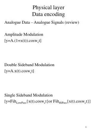
Modulation of a digital signal for transmission on a bandpass channel
Transmission Impairment • Attenuation • Distortion • Noise
Transmission medium Signal Attenuation • Attenuation Loss of energy • Signal strength falls off with distance • Attenuation depends on medium • Attenuation is an increasing function of frequency
Point 1 Point 2 Relative Signal Strength • Measured in Decibel (dB) • P1 and P2 are signal powers at points 1 and 2, respectively • Positive dB signal is amplified (gains strength) • Negative dB signal is attenuated (loses strength) dB = 10 log10 (P2/P1)
Example Sometimes the decibel is used to measure signal power in milliwatts. In this case, it is referred to as dBm and is calculated as dBm = 10 log10 Pm , where Pm is the power in milliwatts. Calculate the power of a signal with dBm = −30. Solution We can calculate the power in the signal as
Example The loss in a cable is usually defined in decibels per kilometer (dB/km). If the signal at the beginning of a cable with −0.3 dB/km has a power of 2 mW, what is the power of the signal at 5 km? Solution The loss in the cable in decibels is 5 × (−0.3) = −1.5 dB. We can calculate the power as
Signal Distortion • Distortion Change in signal shape • Only happens in guided media • Propagation velocity varies with frequency
Noise • Noise Undesirable signals added between the transmitter and the receiver • Types of noise • Thermal • Due to random motion of electrons in a wire
Wire 1 Wire 2 Noise • Types of noise (cont’d) • Crosstalk • Signal from one line picked up by another • Impulse • Irregular pulses or spikes • E.g., lightning • Short duration • High amplitude
Signal-to-Noise Ratio • Signal-to-Noise Ratio (SNR)
Example The power of a signal is 10 mW and the power of the noise is 1 μW; what are the values of SNR and SNRdB ? Solution The values of SNR and SNRdB can be calculated as follows:
Data Rate: Noiseless Channels • Nyquist Theorem • Bit rate in bps • Bandwidth in Hz • L – number of signal levels Bit Rate = 2 × Bandwidth × log2L Harry Nyquist(1889-1976)
Example We need to send 265 kbps over a noiseless channel with a bandwidth of 20 kHz. How many signal levels do we need? Solution We can use the Nyquist formula as shown: Since this result is not a power of 2, we need to either increase the number of levels or reduce the bit rate. If we have 128 levels, the bit rate is 280 kbps. If we have 64 levels, the bit rate is 240 kbps.
Data Rate: Noisy Channels • Shannon Capacity • Capacity (maximum bit rate) in bps • Bandwidth in Hz • SNR – Signal-to-Noise Ratio Capacity = Bandwidth × log2(1+SNR) Claude Elwood Shannon(1916-2001)
Example A telephone line normally has a bandwidth of 3000. The signal-to-noise ratio is usually 3162. Calculate the theoretical highest bit rate of a regular telephone line. This means that the highest bit rate for a telephone line is 34.860 kbps. If we want to send data faster than this, we can either increase the bandwidth of the line or improve the signal-to-noise ratio.
Example We have a channel with a 1-MHz bandwidth. The SNR for this channel is 63. What are the appropriate bit rate and signal level? Solution First, use the Shannon capacity followed by the Nyquist formula
Note The Shannon capacity gives us the upper limit; the Nyquist formula tells us how many signal levels we need.
Network Performance • Bandwidth • Hertz • Bits per second (bps) • Throughput • Actual data rate • Latency (delay) • Time it takes for an entire message to completely arrive at the destination
Latency • Composed of • Propagation time • Transmission time • Queuing time • Processing time Entire message propagation time transmission time
Propagation time Transmission time Latency Receiver Sender First bit leaves Data bits First bit arrives Last bit leaves Last bit arrives Time Time
Bandwidth-Delay Product • The link is seen as a pipe • Cross section = bandwidth • Length = delay • Bandwidth-delay product defines the number of bits that can fill the link