Download

1 / 18
180 likes | 343 Vues
Dual-rate burst upstream. Frank Effenberger Huawei Technologies Kenichi Suzuki NTT March 2007 . Introduction. An Ad-hoc was formed to consider the burst mode reception at 2 bit rates problem

E N D
Dual-rate burst upstream Frank Effenberger Huawei Technologies Kenichi Suzuki NTT March 2007
Introduction • An Ad-hoc was formed to consider the burst mode reception at 2 bit rates problem • This presentation discusses the basic design of optical receivers, to develop scaling rules for bandwidths and design variants • This should allow the membership to make educated judgments when choosing alternatives that impact speed/sensitivity
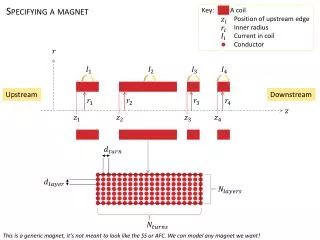
Photodetectors • PIN diode • Responsivity (A/W) • Dark current (nA) • Intrinsic capacitance (pF) • Transit time (ps) • APD • All the above, plus… • Gain () • Excess Noise Factor ()
Noise, and the first amplifier • There are several noise sources • RIN noise (from the transmitter) • Shot noise (from signal and dark current) • Excess noise (from avalanche gain process) • Thermal noise (from the circuit itself) • In PIN receivers, thermal noise dominates • In APDs, shot and excess noise play a role • The SNR out of the first amplifier tells the story in any (properly designed) circuit
Trans-Impedance Amplifier • All modern optical PMDs use this topology • The key idea is that the amplifier’s gain reduces the effective impedance as regards the speed of response • Thus, a higher impedance value can be used (better SNR) while maintaining a high response speed (faster)
_ + Circuit Vb R C Ip B2 = final LPF A Vout
Signal to Noise Ratio • When thermal noise limited, • SNR ~ Ps2R/B2 ~ (Ps/B1) (Ps/B2) • For a fixed SNR: Ps~(B1B2)1/2 • When shot noise limited, • SNR ~ Ps/B2 • For a fixed SNR: Ps~B2
The dual-rate problem • Signals come in at different rates • OLT must either • Parallel process signal at both speeds (and decide later which was right), or • Serially process signals at one speed • This decision has to do with choice of detector technology, and whether we are thermal noise limited or shot noise limited
_ + Parallel PMD Circuit Vb R C 1Gb/s Signal 10 Gb/s signal Ip B21 = 1 GHz LPF A B22 = 8 GHz LPF Thermal-limited: Shot-limited:
_ + Serial PMD Circuit Vb Control signal R2 R1 C 1Gb/s Signal 10 Gb/s signal Ip B21 = 1 GHz LPF A B22 = 8 GHz LPF Thermal-limited: Shot-limited:
Comparison of Serial and Parallel • In shot-limited case, there is no difference • Pre-amp circuit does not impact SNR • In thermal-limited case, the Parallel circuit 1G SNR is degraded by factor B1/B12 = 8 • Constant SNR power penalty = 4.5 dB
APD receivers • Practical APD receivers fall midway between these two extremes • The setting of the multiplication factor M balances thermal noise versus excess noise (akin to shot noise) • So, in APD receivers, we have THREE effective bandwidths to play with • B2: The bandwidth of the post-amp (easy) • B1: The bandwidth of the pre-amp (moderate) • B0: The ‘bandwidth’ of the M setting (hard to do)
SNR for APD with an optimized gain This resistance would be the ideal TIA resistance for whatever speed we are optimizing.
Sensitivity as a function of the three bandwidths • For an B0 Gbit/s optimized APD: • For fixed SNR:
Achieving the 29 dB budget • The 29 dB budget of 1G-EPON is achieved with -27.6 dBm OMA (this is -29.7 dBm sensitivity at ER=10dB) • Scaling this to 10G, we obtain • None of these seem unbelievable • Parallel receiver may squeeze margins
Conclusions • We can utilize serial and parallel configurations with APDs for upstream 10G/1G coexistence • The parallel configuration with 10G optimized APD is simpler compared to serial configuration • Half-serial configuration provides about 1 dB more sensitivity in 1G mode • But we need to realize comparatively higher sensitivity receivers or higher power transmitter to realize 29 dB CIL even if we apply FEC to 10G receivers