Download
1 / 23
230 likes | 365 Vues
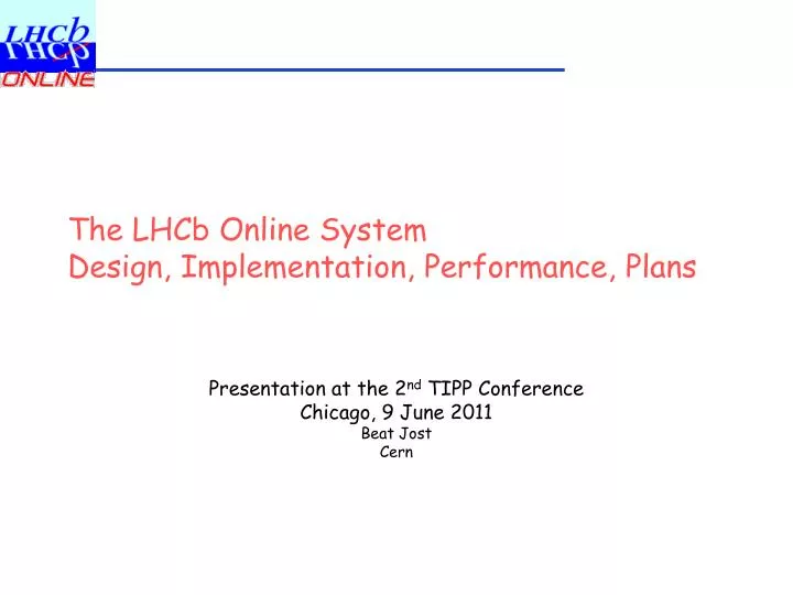
The LHCb Online System Design, Implementation, Performance, Plans. Presentation at the 2 nd TIPP Conference Chicago, 9 June 2011 Beat Jost Cern. The LHCb Detector.

E N D
The LHCb Online SystemDesign, Implementation, Performance, Plans Presentation at the 2nd TIPP Conference Chicago, 9 June 2011 Beat Jost Cern
The LHCb Detector Single-arm spectrometer composed of Vertex Locator, Tracking System, RICH detectors, Calorimeter System (Preshower, ECAL, HCAL) and Muon system to explore the strongly forward peaked bb production at the LHC TIPP 2, Chicago, 9 June 2011
System Requirements/Boundary Conditions • Bunch-Crossing rate: 40 MHz • Luminosity in LHCb: ~0.2 Hz/nb • Interaction rate in LHCb: ~15 MHz • Hardware Trigger accept Rate: 1 MHz (max) • Given by readout time from detector electronics to readout electronics (36 clock cycles of 25 ns) • Detector channels: ~1 Million • Event Size (after Zero Suppression): ~60kB • Original design value ~35 kB • High-Level Trigger output rate (rate to tape): • 3 kHz physics + 1 kHz other • Originally: 200 Hz TIPP 2, Chicago, 9 June 2011
System Design Criteria • Simplicity • Simple protocols, commercial solutions wherever possible • Scalability • Capable of absorbing new and changing requirements • Uniformity • Common solution for common problem • Identical behaviour as early as possible in the readout • As few technologies as possible • Operability • Operate the experiments with minimal number of people on shift • Partitionability • Ability to operate disjoint parts of the detector independently and asynchronously • Robustness • Strict separation of control and data path • No Buses, only point-point connections TIPP 2, Chicago, 9 June 2011
System Architecture TIPP 2, Chicago, 9 June 2011
Subsystems • The entire Online system is decomposed into three major Sub-systems • Experiment Control System (formerly Slow control) • Control, Configuration and Monitoring of the entire Online system • Includes • Classical slow control (Temperatures, Low/High Voltages, gases,…) • Readout Hardware • Readout software • Trigger software • Run Control • Timing And Fast Control System (TFC) • Generate and distribute all beam-synchronous information to the readout layer and the front-end electronics, such as • Clock • Trigger decisions • Beam-synchronous commands, e.g. resets, calibration commands • Data Flow system (aka. DAQ system) • Data transfer from Front-end electronics to storage • Provide infrastructure for the High-Level Trigger software TIPP 2, Chicago, 9 June 2011
Experiment Control System * Now called “SIMATIC WinCC Open Architecture” • Based on commercial control framework (ETM PVSS-II*) • Hierarchical design • Control UnitsControl Units…Device Units • Highly distributed across some 150 Control PCs TIPP 2, Chicago, 9 June 2011
Control and Device Units • Control Units implement behaviour • Based on PVSS-II and SMI++ Finite State Machine tool and DIM communication Device Units control HW/SW devices via commercial (OPC servers) or in-house software drivers. Interfaces to the FSM software providing state information TIPP 2, Chicago, 9 June 2011
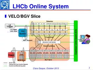
Timing and Fast Control LHC Clock/Turn Resets L0 Trigger Decision Readout Supervisor Clock/Trigger TFC switch Throttle switch 16x16 Switch Throttle Throttle OR Opt. FanOut Throttle OR Opt. FanOut Subdetectorn Front-End Electronics Subdetectorn Front-End Electronics Subdetectorn Readout Electronics Subdetectorn Readout Electronics Interface between the LHCb trigger system, the LHC machine and the readout electronics (simplified) Architecture TIPP 2, Chicago, 9 June 2011
Timing and Fast Control • Readout Supervisor (RS) central component of the subsystem. • Custom board based on FPGAs • Handles trigger and clock inputs and forwards them towards readout electronics • Ensures buffer overflow protection (Rate control) • Emulation of front-end electronics behaviour (synchronous) • Obeying throttle signal (asynchronous) • Signal transmission based on Cern’s TTC (Timing and Trigger Control) optical transmission system. • Partitioning support through the TFC and throttle switches • Guide the signals from the RS towards the detector electronics and the throttle signals back to the same RS • Allows for up to 16 parallel activities TIPP 2, Chicago, 9 June 2011
Data Acquisition System • System Components • Detector Readout Units • Readout Network • GbEthernet • CPU farm • Storage subsystem TIPP 2, Chicago, 9 June 2011
Detector Readout Units (aka Tell1) • Custom board based on FPGA • Common board for (almost) all subdetectors • Functionality • Receive data from front-End electronics • Alternatively • Up to 24 optical GOL links (24x1.28 Gb/s = 30 Gb/s) • Up to 64 electrical analog links (64*10b*40 MHz = 25 Gb/s) • Detector specific processing of the data • Zero suppression, clustering etc.. • Data formatting • Output data to destination transmitted by TFC system • 4 GbEthernet output ports TIPP 2, Chicago, 9 June 2011
Readout Network MRJ21 Connector 6x1000BaseT • Based on Gb Ethernet • Low price, high performance, mature, scalable, large speed range, longevity • Required Throughput >80 GB/s • >800 input links • >600 output links • Large buffers (256 MB/48 ports) • Implementation • 2 Force10 E1200 chassis each containing • 10 90-port copper GbEthernet ports TIPP 2, Chicago, 9 June 2011
CPU Farm • Provides the infrastructure for the high-level trigger • Required CPU power obviously depends on time per event of the triggering algorithm • Currently ~20 ms per event • @ 1MHz input rate ~20000 copies of the trigger task neededcurrently 1350 Processing elements (boxes) • Two types of Processors • 550 boxes dual Intel Harpertown (8 physical Cores) • 800 boxes dual Intel Westmere (12 physical Cores) • Organized in 50 subfarms (racks) TIPP 2, Chicago, 9 June 2011
Farm Implementation Control Network From Readout Network 12x 1Gb SubFarm Data Switch(48ports) SubFarm ControlSwitch(48 ports) 1Gb 1Gb CPU CPU CPU x27 CPU CPU 50 Subfarms (Racks) with identical layout Architecture TIPP 2, Chicago, 9 June 2011
Resultant Implementation • Each DRU has either two or four links into the readout network • Equal number into each switch chassis • From each switch chassis there are 6 links into each subfarm • The CPU farm consists (today) of 1350 boxes (14000 physical cores) • 365 Detector readout Units • 1560 GbEthernet links in/out of main DAQ switches • 1350 GbEthernet links into the farm CPUs • ~1000 GbEthernet links for controls network TIPP 2, Chicago, 9 June 2011
Data Transfer Protocols • In general data are pushed through the system without acknowledgment (“fire and forget”) • Simple data sources • Little/no buffering needed • No protocol handling • Assumes only very few packets are lost on the way… • Upon L0-trigger “Yes” the detector front-end electronics push the data through the GOL links towards the DRUs • The DRUs do all the necessary processing and push the data towards the CPU farm • Events (triggers) are packed into Multi-Event Packets (MEP). The packing factor is configurable and ~10 • Reduction of the transport overheads (Ethernet and IP headers) • The data format through the readout network is raw IP packets • The destination (Farm node) is assigned by the RS and conveyed through the TFC network to each DRU. TIPP 2, Chicago, 9 June 2011
Rate Limitation/Overload protection • Reasons for overload • The front-end electronics has a limited de-randomizing buffer of 16 events. At a readout speed of 900 ns/event this buffer could overflow • At this level the system is completely synchronous to the (LHC) clock • Thus the Readout Supervisor can predict when the buffer would be overfilled conversion of trigger “Yes” to “No” • The output buffer of the DRUs could fill up because of to high data rate • System at this level is asynchronous • DRUs assert throttle signal towards the RS to stop data from flowing in • The CPU farm can be busy • Each farm node signals its readiness to receive data to the RS with a MEP request packet. • RS will throttle trigger when there are no open MEP requests TIPP 2, Chicago, 9 June 2011
Operations • The experiment and the online system is operated using point-and-click panels, based on the PVSS toolkit • Behaviour and sequencing is achieved using the SMI++ state management Toolkit • Many automatic actions • Recovering dead HLT tasks • Raising/lowering HV depending on LHC state • Allows operating the entire detector with 2 people on shift TIPP 2, Chicago, 9 June 2011
System Performance The system is currently operated at 660kHz trigger rate Event size is ~55kB (design 34 kB) Data rate through readout network into the farm ~36 GB/s HLT output Rate (rate to tape) ~40 kHz (design 200 Hz) Dead-Time (due to rate limiting) ~5% (mainly due to non-conformity of Front-End Electronics) TIPP 2, Chicago, 9 June 2011
Readout Network Cabling TIPP 2, Chicago, 9 June 2011
DRU Cabling TIPP 2, Chicago, 9 June 2011
Upgrade plans • Eliminate the hardware trigger • Aim is to improve trigger efficiency, mainly hadron trigger • Readout full detector at bunch-crossing rate, i.e. 40 MHz • Perform event selection in software in the CPU farm • Consequences • New detector front-end electronics • Zero-suppression at front-end electronics • 40-fold increase in data rate • ~40-fold increase in CPU power • New TFC system, same philosophy • Strategy • Replace GbEthernet with 10Gb technology (prob. Ethernet) • replace GOL with GBT link (~x3 in bandwidth) • Replace CPU farm with new generation processors x ~4 • Timescale: ~2016/7, or so... TIPP 2, Chicago, 9 June 2011