Download
1 / 20
210 likes | 1.32k Vues
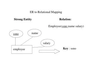
Chapter 4 Part 2 Relational Database Design by ER and EER-to-Relational Mapping. Mapping EER Model Constructs to Relations. Step8: Options for Mapping Specialization or Generalization.

E N D
Chapter 4 Part 2Relational Database Design by ER and EER-to-Relational Mapping
Mapping EER Model Constructs to Relations • Step8: Options for Mapping Specialization or Generalization. • Convert each specialization with m subclasses {S1, S2,….,Sm} and generalized superclass C, where the attributes of C are {k,a1,…an} and k is the (primary) key, into relational schemas using one of the four following options: • Option 8A: Multiple relations-Superclass and subclasses • Option 8B: Multiple relations-Subclass relations only • Option 8C: Single relation with one type attribute • Option 8D: Single relation with multiple type attributes
Mapping EER Model Constructs to Relations • Option 8A: Multiple relations-Superclass and subclasses • Create a relation for the superclass and its attributes, plus a relation for each subclass includes the local attributes of it , plus the primary key of the superclass which is propagated to subclass relation and becomes its primary key also. It also becomes a foreign key to the superclass relation. • Option 8A works for any constraints on the specialization: disjoint or overlapping, total or partial. • Option 8B: Multiple relations-Subclass relations only • Create a relation for each subclass includes the local attributes of the superclass. The primary key of the superclass is propagated to subclass relation and becomes its primary key. • Option 8 B works for only when both the disjoint and total constraints hold.
Mapping EER Model Constructs to Relations • Disjoint constraints: A member of the superclass needs to be a member of one subclass only. We use d inside the circle symbol. • Overlapping constraints: A member of the superclass could be a member in more than one subclass. We use o inside the circle symbol. • Total completeness constraint: the member of the superclass need to be only a member in subclasses we have. Double lines in ER diagram • Partial completeness constraint: The member of the superclass is a member of other subclasses than the ones we have. One line
FIGURE 4.4EER diagram notation for an attribute-defined specialization on JobType.
FIGURE 7.4Options for mapping specialization or generalization. (a) Mapping the EER schema in Figure 4.4 using option 8A.
FIGURE 4.3Generalization. (b) Generalizing CAR and TRUCK into the superclass VEHICLE.
FIGURE 7.4Options for mapping specialization or generalization. (b) Mapping the EER schema in Figure 4.3b using option 8B. Eng Type
Mapping EER Model Constructs to Relations (continued) • Option 8C and 8D: • Create a single relation to represent the superclass and all its subclasses. • An entity that does not belong to some of the subclasses will have NULL values for the specific attributes for these subclasses. • These options are not recommended if many specific attributes are defend for the subclasses. • If few specific subclass attributes exist. However, these mapping are preferable to option 8A and 8B because they do away with the need to specify EQUIJOIN and OUTER UNION operations: therefore, they can yield a more efficient implementation. • Option 8C: Single relation with one type attribute. • Is used to handle disjoint subclasses by including a single type or discrimination attribute t to indicate to which of the subclasses each tuple belongs: hence, the domain of t could be {1, 2, …….m}. If the specialization is partial, t can have NULL values in tuples that do not belong to any subclass. • Option 8D: Single relation with multiple type attributes. • Is used handle overlapping subclasses by including m Boolean type (or flag) fields, one for each subclass. It can also be used for disjoint subclasses. • Each type filed t can have a domain(yes, no), where a value of yes indicates that the tuple is a member of subclass S.
FIGURE 4.4EER diagram notation for an attribute-defined specialization on JobType.
FIGURE 7.4Options for mapping specialization or generalization. (c) Mapping the EER schema in Figure 4.4 using option 8C. Eng Type
FIGURE 4.5EER diagram notation for an overlapping (nondisjoint) specialization.
FIGURE 7.4Options for mapping specialization or generalization. (d) Mapping Figure 4.5 using option 8D with Boolean type fields Mflag and Pflag.
Mapping EER Model Constructs to Relations (continued) • Mapping of Shared Subclasses (Multiple Inheritance) A shared subclass, such as STUDENT_ASSISTANT, is a subclass of several classes, indicating multiple inheritance. These classes must all have the same key attribute; otherwise, the shared subclass would be modeled as a category. We can apply any of the options discussed in Step 8 to a shared subclass, subject to the restriction discussed in Step 8 of the mapping algorithm. Below both 8C and 8D are used for the shared class STUDENT_ASSISTANT.
FIGURE 4.7A specialization lattice with multiple inheritance for a UNIVERSITY database.
FIGURE 7.5Mapping the EER specialization lattice in Figure 4.6 using multiple options.
Mapping EER Model Constructs to Relations (cont) • Step 9: Mapping of Union Types (Categories). • For mapping a category whose defining superclass have different keys, it is customary to specify a new key attribute, called a surrogate key, when creating a relation to correspond to the category. • In the example below we can create a relation OWNER to correspond to the OWNER category and include any attributes of the category in this relation. The primary key of the OWNER relation is the surrogate key, which we called OwnerId.
FIGURE 4.8Two categories (union types): OWNER and REGISTERED_VEHICLE.
FIGURE 7.6 Mapping the EER categories (union types) in Figure 4.7 to relations.
Mapping Exercise Exercise 7.4. FIGURE 7.7An ER schema for a SHIP_TRACKING database.