Download
1 / 37
370 likes | 551 Vues
EIC Overview. (mainly EIC@JLab accelerator and detector parameters). Lots of credit to Yuhong Zhang, Alex Bogacz, Slava Derbenev, Geoff Krafft, Tanja Horn, Charles Hyde, Pawel Nadel-Turonski for multiple accelerator and detector/interaction region ideas. Rolf Ent

E N D
EIC Overview (mainly EIC@JLab accelerator and detector parameters) Lots of credit to Yuhong Zhang, Alex Bogacz, Slava Derbenev, Geoff Krafft, Tanja Horn, Charles Hyde, Pawel Nadel-Turonski for multiple accelerator and detector/interaction region ideas Rolf Ent Nuclear Chromo-Dynamic Studies with a Future EIC Workshop at Argonne National Laboratory April 07-09, 2010
EIC Project - Status NSAC 2007 Long-Range Plan: “An Electron-Ion Collider (EIC)with polarized beams has been embraced by the U.S. nuclear science community as embodying the vision for reaching the next QCD frontier. EIC would provide unique capabilities for the study of QCD well beyond those available at existing facilities worldwide and complementary to those planned for the next generation of accelerators in Europe and Asia.”
Current Ideas for a Collider Design Goals for Colliders Under Consideration World-wide Present focus of interest (in the US) are the (M)EIC and Staged MeRHIC versions, with s up to 2650 and 4000, resp.
4 GeV e x 250 GeV p – 100 GeV/u Au MeRHIC 2 x 60 m SRF linac 3 passes, 1.3 GeV/pass s = 800 - 4000 Polarized e-gun Beam dump MeRHIC detector 3 pass 4 GeV ERL PHENIX • MeRHIC • Medium Energy eRHIC • @ IP2 of RHIC (IP12?) • Up to 4 GeV e- x 250 GeV p • L ~ 1032-1033cm-2 sec -1 STAR V.N. Litvinenko, RHIC S&T Review, July 23, 2009
A High-Luminosity EIC at JLab - Concept Note: sHERMES= 51 unpol. L = 1032+ sCOMPASS = 340 unpol. L = 1032 sCOMPASS++ = 340 L = 1032+ Legend: MEIC = EIC@JLab 1 low-energy IR (s ~ 200) 2 medium-energy IRs (s < 2600) ELIC = high-energy EIC@JLab (s = 11000) (Ep ~ 250 limited by JLab site) Use CEBAF “as-is” after 12-GeV Upgrade
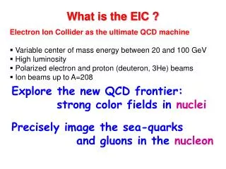
EIC@JLab assumptions: (x,Q2) phase space directly correlated with s (=4EeEp) : @ Q2 = 1 lowest x scales like s-1 @ Q2 = 10 lowest x scales as 10s-1 x = Q2/ys General science assumptions: (“Medium-Energy”) EIC@JLab option driven by: access to sea quarks (x > 0.01 or so) deep exclusive scattering at Q2 > 10 (?) any QCD machine needs range in Q2 s = few 100 - 1000 seems right ballpark s = few 1000 allows access to gluons, shadowing Requirements for deep exclusive and high-Q2 semi-inclusive reactions also drives request for (lower &) more symmetric beam energies. Requirements for very-forward angle detection folded in IR design
MEIC/ELIC Design Goal • Energy Wide CM energy range between 10 GeV and 100 GeV • Low energy: 3 to 11 GeV e on 3 to 12 GeV p (and ion) • Medium energy: up to 11 GeV e on 60 GeV p or 24 GeV/n ion and for future upgrade • High energy: up to 11 (22?) GeV e on 250 GeV p or 100 GeV/n ion • Luminosity • 1033 up to 1035 cm-2s-1per collision point • Multiple interaction points • Ion Species • Polarized H, D, 3He, possibly Li • Up to heavy ion A = 208, all stripped • Polarization • Longitudinal at the IP for both beams, transverse for ions • Spin-flip of both beams • All polarizations >70% desirable • Positron Beamdesirable
MEIC Design Choices Achieving high luminosity • Very high bunch repetition frequency (1.5 GHz) • Very small β* to reach very small spot sizes at collision points • Short bunch length (σz~ β*) to avoid luminosity loss due to hour-glass effect (unless other mitigation schemes used) • Relatively small bunch charge for making short bunch possible • High bunch repetition restores high average current and luminosity This luminosity concept has been tested at two B-factories very successfully, reaching luminosity above 1034 cm-2/s-1 • MeRHIC • Low repetition rate • Very high bunch charge • Long bunch length • Largeβ* • MEIC • High repetition rate • Small bunch charge • Short bunch length • Small β* • VS.
MEIC Design Choices (cont.) • Ring-ring vs. Linac(ERL)-ring • Linac-ring option requires very high average current polarized electron sources (few decades times state-of-the-art) • Linac-ring option does not help ELIC which already employs high repetition electron and ion beams ring-ring collider • Ensuring high polarization for both electron beam and light ion beams Figure-8 shape rings • Simple solution to preserve full ion polarization by avoiding spin resonances during acceleration • Energy independence of spin tune • g-2 is small for deuterons; a figure-8 ring is the only practical way to arrange for longitudinal spin polarization at the IP
MEIC Luminosity: Energy Dependence • MEIC luminosity is limited by • Electron beam current synchrotron radiation ~ Neγ4/ρ (radiation power, emittance degradation) • Proton/ion beam current space charge effect ~ Ni/γ2 (emittance growth, tune-shift/instabilities) • (Vertical) beam-beam tune-shift (bad collisions) ~ 1/γ • Main design limits (based on experience) • Electron beam SR power density: ≤ 20 kW/m • Ion beam space charge tune-shift: ≤ 0.1 • (Vertical) beam-beam tune-shift: ≤ 0.015 (proton), ≤ 0.1 (electron) • Given an energy range, MEIC collider ring optimized with • Synchrotron radiation prefers a large ring (for more arc bends) • Space charge effect of i-beam prefers a small ring circumference • Multi IPs and other components require long straight sections
MEIC Luminosity with a Compact Ring • 660 m ring circumference was determined to be the minimum arc length required to accommodate 60 GeV protons in a Figure-8 ring • Illustration is based on back-of-envelope estimations, using three main design limits, omitting more complicated beam dynamics issues • Given the ring size, the synchrotron limit determines the optimal luminosity/electron energy. Beyond this electron energy a fast drop. Just an illustration
MEIC Luminosity with a Compact Ring • Luminosity of 60 GeV protons in a 1 km ring, based on a back-of-the-envelope calculation, is lower than in 0.6 km ring, since space charge effects are more severe in a larger ring • Luminosity of 100 GeV protons is on the other hand much better in a 1 km ring, since space charge effects are reduced with higher energy • Consider what the minimum luminosity is at both lower and higher ion energies! Just an illustration
Near-Term MEIC Design Parameters Luminosity expected to reach up to 1 x 1034 e-nucleons/s/cm2 around 60x5 GeV2
Detector/IR in simple formulas bmax ~ 2 km = l2/b*(l = distance IP to 1st quad) Example: l = 7 m, b* = 20 mm bmax = 2.5 km IP divergence angle ~ 1/sqrt(b*) Example: l = 7 m, b* = 20 mm angle ~ 0.3 mr Example: 12 s beam-stay-clear area 12 x 0.3 mr = 3.6 mr ~ 0.2o Making b* too small complicates small-angle (0.5o?) detection before ion Final Focusing Quads, AND would require too much focusing strength of these quads, preventing large apertures (up to 0.5o?) Luminosity ~ 1/b*
Figure-8 Ion Ring – Optics Uncompensated dispersion from arcs Arc length C = 120 m + 20 m (for spin manipulation) + 120 m (increased due to assumption of 60 GeV & 6T max dipole fields) Straight length L = 194 m Total Ring Circumference would then be: 2 (L + C) = 908 m
Interaction Region Optics (ions) IP f l * = 7m FF triplet : Q3 Q2 Q1 Natural Chromaticity: x = -44 y = -137 Q1 G[kG/cm] = -9.7 Q2 G[kG/cm] = +6.7 Q3 G[kG/cm] = -6.3 Q3 aperture 10 cm (@12 m) 7T peak field Particles < 0.5 degrees through FF quads
Figure-8 Collider Rings (Reminder: MEIC/ELIC scheme uses 100 mr crab crossing) Present thinking: ion beam has 100 mr horizontal crossing angle Advantages for dispersion, crab crossing, very-forward particles 200 mr bend would need 40 Tm dipole @ ~20 m from IP total ring circumference: 908 m 64 degrees arc/straight crossing angle
Ion Ring – Beam envelopes FF Quads @ about 10 m, sx,y = 2-3 mm Very forward tagging? ~ 20 meters sx,y = 0.2 mm IP Beam-stay-clear area near IP: 10-12 s 5 cm @ 10 m = 5 mr Beam-stay-clear area away from IP: 8-10 s 2 mm @ 20 m = 0.1 mr
Overview of central detector layout (not to scale) Solenoid yoke integrated with a hadronic calorimeter and a muon detector Time-of-flight detectors shown in green Hadronic calorimeter EM calorimeter Muon Detector? EM calorimeter EM calorimeter RICH HTCC RICH (DIRC?) ions Tracking electrons DIRC would have thin bars arranged in a cylinder with readout after the EM calorimeter on the left • IP is shown at the center, but can be shifted left • Determined by desired bore angle and forward tracking resolution • Flexibility of shifting IP also helps accelerator design at lower energies (gap/path length difference induced by change in crossing angle)
4 on 30 GeV 5 on 50 GeV (10 on 50 GeV) s = 480 GeV2 s = 1000 GeV2 s = 2000 GeV2 Detector/IR - Kinematics • Vertical lines at 30° (possibly up to 40°) indicate transition from central barrel to endcaps • Horizontal line indicates maximum meson momentum for π/K separation with a DIRC Q2 > 10 GeV2 • With 12 GeV CEBAF, MEIC@JLab has the option of using higher electron energies • DIRC no longer sufficient for π/K separation • RICH based on ALICE design might push the limit from 4 to 7 GeV • Requires a more detailed study • RICH would extend the minimum diameter of solenoid from approximately 3 to 4 m • Main constraint since bore angle is not an issue in JLab kinematics
Detector/IR – Particle Momenta SIDIS p 1H(e,e’π+)n 4 on 60 11 on 60 { { Need Particle ID for p > 4 GeV in central region DIRC won’t work, need more space for RICH Need Particle ID for well above 4 GeV in forward region (< 30o?) determines bore of solenoid In general: region of interest up to ~10 GeV/c mesons (not including very-forward angle detection, see later)
Detector/IR – Magnetic Fields Pion momentum = 5 GeV/c, 4T ideal solenoid field • Resolution dp/p (for pions) better than 1% for p < 10 GeV/c • obtain effective 1Tm field by having 100 mr crossing angle • 200 mr ~ 12o gives effective 2Tm field • need to add 1-2Tm dipole field for small-angle pions (1o-6o) only Add 2Tm transverse field component to get dp/p roughly constant vs. angle
Detector/IR cartoon Make use of a 100 mr crossing angle for ions! (approximately to scale) detectors solenoid ion FFQs ion dipole w/ detectors ions IP 0 mrad electrons electron FFQs 100 mrad 2+3 m 2 m 2 m 0.2 - 2.5° 4 on 30 GeV Q2 > 10 GeV2 • Downstream dipole on ion beam line has several advantages • No synchrotron radiation • Electron quads can be placed close to IP • Dipole field not determined by electron energy • Positive particles are bent away from the electron beam • Long recoil baryon flight path gives access to low -t • Dipole does not interfere with RICH and forward calorimeters • Excellent acceptance (hermeticity) recoil baryons exclusive mesons
Detector/IR – Forward Angles t ~ Ep2Q2 Angle recoil baryons = t½/Ep Example: map t between tmin and 1 (2?) GeV 0.2 to 4.9 (9.8) degrees @ 12 GeV 0.2 to 3.0 (5.9) degrees @ 20 GeV 0.2 to 2.0 (3.9) degrees @ 30 GeV • Cover between about 0.5 and 6 degrees? Example I: separation between 0.5o and 0.2o (BSC) ~ 2.5 cm at 5 meter distance May be enough for ~ 30 GeV protons and neutrons from an O(1A) beam (also need good angle (t) resolution!) Example II: 6 degrees ~ 0.5 meter radius cone at 5 meter
Detector/IR – Forward Angles t ~ Ep2Q2 Angle recoil baryons = t½/Ep Ep = 12 GeV Ep = 30 GeV Ep = 60 GeV DQ = 1.3 DQ = 5 • Must cover between 1 and 5 degrees • Should cover between 0.5 and 5 degrees • Like to cover between 0.2 and 7 degrees
Detector/IR – Very Forward • Ion Final Focusing Quads (FFQs) at 7 meter, allowing ion detection down to 0.5obefore the FFQs • Use large-aperture (10 cm radius) FFQs to detect particles between 0.3 and 0.5o (or so) in few meters after ion FFQ triplet • sx-y @ 12 meters from IP = 2 mm • 12 s beam-stay-clear 2.5 cm • 0.3o (0.5o) after 12 meter is 6 (10) cm • enough space for Roman Pots & • “Zero”-Degree Calorimeters • Large dipole bend @ 20 meter from IP (to correct the 100 mr ion horizontal crossing angle) allows for very-small angle detection (< 0.3o) • sx-y @ 20 meters from IP = 0.2 mm • 10 s beam-stay-clear 2 mm • 2 mm at 20 meter is only 0.1 mr… • D(bend) of 29.9 and 30 GeV spectators is 1.3 mr = 5 mm @ 4 m • Situation for zero-angle n detection very similar as at RHIC!
Forward Neutron Detection Thoughts – A Zero Degree Calorimeter The RHIC Zero Degree Colorimeters arXiv:nucl-ex/0008005v1 Context: The RHIC ZDC’s are hadron calorimeters aimed to measure evaporation neutrons which diverge by less than 2 mr from the beam axis. <2 mr at 18 meters from IP neutron cone ~ 4 cm ZDC = 10 cm (horizontal) x 13 cm (vertical) (& 40 cm thick) Have good efficiency and only 1 cm “dead-edge” (albeit not very good DE resolution). Implication: do not make earlier ion bend dipole strong < 2 TM!
EIC Overview - Summary • Near-term design concentrates on parameters that are within state-of-the-art (exception: small bunch length & small vertical b* for proton/ioan beams) • Detector/IR design has concentrated on maximizing acceptance for deep exclusive processes and processes associated with very-forward going particles • Exact energy/luminosity profile still a work in progress • Summer 2010: MEIC design review followed by internal cost review (and finalizing input from user workshops) • Many parameters related to the detector/IR design seem to be well matched now (crossing angles, magnet apertures/gradients/peak fields, field requirements), such we may end up with not too many “blind spots”.
Proton Tagging • 100 mr horizontal crossing angle for ion beam would require large 40Tm magnet at 20 meter from the IP. If so, can need this for spectator proton tagging • D(bend) 30 GeV vs. 29.9 GeV = 1.3 mr • If roman pots after 4 m 5 mm bend • 1% (300 MeV/c) would become 15 mm • Roman pots (photos at CDF (top) and LHC (bottom), …) ~ 1 mm from beam achieve proton detection with < 100m resolution • Proton tagging concept looks doable, even if the horizontal crossing angle was reduced by a factor of two or three.
Neutron Tagging The RHIC Zero Degree Colorimeters arXiv:nucl-ex/0008005v1 • EIC@JLab case: 40 Tm bend magnet at 20 meters from IP very comparable to above RHIC case! • 40 Tm bends 60 GeV protons with 2 times 100 mr • deflection @ a distance of about 4 meters = 80 cm (protons) • no problem to insert Zero Degree Calorimeter in this design • Zero Degree Calorimeter properties: • Example: for 30 GeV neutrons get about 25% energy resolution (large constant term due to unequal response to electrons and photons relative to hadrons) • Should be studied more whether this is sufficient • Timing resolution ~ 200 ps • Very radiation hard (as measured at reactor)
(M)EIC@JLab: Where we are x = Q2/ys HERA experience: Can map between y = 0.8 and y = 0.004 @ s = 1200 & x = 0.8: 12 (W2 = 4) < Q2 < 640 @ s = 2640 & Q2 = 1: down to x = 4.7x10⁻⁴ Note: for deuteron Z/A = 0.5 for heavy ion Z/A = 0.4 • Design provides excellent luminosity for s ~ 1000 • Good luminosity (1033 or more???) down to s = 240 and up to s = 2640 • (can access gluons down to x = 0.001 or so)
CTEQ Example at Scale Q2 = 10 GeV2 Gluon splitting dominates “dip” in u,d pdf’s at x ~ 0.01 (@ Q2 =10 GeV2)
The Venerable (Nuclear) EMC Effect F2A/F2D “EMC Effect” 10-4 10-3 10-2 10-1 1 x x < (5 times 10-3) for saturation in shadowing to start? Need about decade in Q2 to verify LT vs. HT of effects want to push down to x ~ 0.0005 (@ Q2 = 1) w. MEIC. Space-Time Structure of Photon Ecm = 10 – 45 (s = 100 – 2000) is in the right ballpark for nucleon/nuclear structure studies
What Ecm and Luminosity are needed for Deep Exclusive Processes? • New Roads: • r and f Production give access to gluon GPD’s at small x (<0.2) • Deeply Virtual Meson • Production @ Q2 > 10 GeV2 Well suited processes for the EIC transverse spatial distribution of gluons in the nucleon Can we do such measurements at fixed x in the valence quark region? Important to disentangle flavor and spin… fixed x: s ~ s/Q2 (Mott) x 1/Q4 (hard gluon exchange)2
‘Relaxed’ IR Optics (electrons) Natural Chromaticity: x = -96 y = -444 IP f l * = 3.5m FF doublets