Download

1 / 13
130 likes | 232 Vues
Chapter 7 Timers. TIMER0 MODULE. The Timer0 module incorporates the following features: Software selectable operation as a timer / counter in both 8-bit or 16-bit modes. Readable and writable registers. Dedicated 8-bit, software programmable prescaler .

E N D
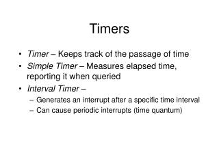
Chapter 7 Timers
TIMER0 MODULE The Timer0 module incorporates the following features: • Software selectable operation as a timer / counter in both 8-bit or 16-bit modes. • Readable and writable registers. • Dedicated 8-bit, software programmable prescaler. • Selectable clock source (internal or external). • Edge select for external clock. • Interrupt-on-overflow.
Timer0 Operation • Timer0 can operate as either a timer or a counter; the mode is selected with the T0CS bit (T0CON<5>). • If the TMR0 register is written to, the increment is inhibited for the following two instruction cycles. • The Counter mode is selected by setting the T0CS bit (= 1). In this mode, Timer0 increments either on every rising or falling edge of pin RA4/T0CKI. • An external clock source can be used to drive Timer0; however, it must meet certain requirements to ensure that the external clock can be synchronized with the internal phase clock (TOSC).
TIMER1 MODULE The Timer1 timer/counter module incorporates these features: • Software selectable operation as a 16-bit timer or counter • Readable and writable 8-bit registers (TMR1H and TMR1L) • Selectable clock source (internal or external) with device clock or Timer1 oscillator internal options • Interrupt-on-overflow • Reset on CCP Special Event Trigger • Device clock status flag (T1RUN)
TIMER1 Operation Timer1 can operate in one of these modes: • Timer • Synchronous Counter • Asynchronous Counter The operating mode is determined by the clock select bit, TMR1CS (T1CON<1>). When Timer1 is enabled, the RC1/T1OSI and RC0/ T1OSO/T13CKI pins become inputs.
TIMER2 MODULE • The Timer2 module timer incorporates the following features: • 8-Bit Timer and Period registers (TMR2 and PR2,respectively) • Readable and writable (both registers) • Software programmable prescaler (1:1, 1:4 and 1:16) • Software programmable postscaler (1:1 through 1:16) • Interrupt on TMR2 to PR2 match • Optional use as the shift clock for the MSSP module
TIMER2 Operation • In normal operation, TMR2 is incremented from 00h on each clock (FOSC/4). The value of TMR2 is compared to that of the Period register, PR2, on each clock cycle. • The TMR2 and PR2 registers are both directly readable and writable. The TMR2 register is cleared on any device Reset, while the PR2 register initializes at FFh. • Both the prescaler and postscaler counters are cleared on the following events: • a write to the TMR2 register • a write to the T2CON register • any device Reset (Power-on Reset, MCLR Reset, • Watchdog Timer Reset or Brown-out Reset) TMR2 is not cleared when T2CON is written.
TIMER3 MODULE • The Timer3 module timer/counter incorporates these features: • Software selectable operation as a 16-bit timer or counter • Readable and writable 8-bit registers (TMR3H and TMR3L) • Selectable clock source (internal or external) with device clock or Timer1 oscillator internal options • Interrupt-on-overflow • Module Reset on CCP Special Event Trigger
TIMER3 Operation Timer3 can operate in one of three modes: • Timer • Synchronous Counter • Asynchronous Counter The operating mode is determined by the clock select bit, TMR3CS (T3CON<1>). When the bit is set, Timer3 increments on every rising edge of the Timer1 external clock input or the Timer1 oscillator, if enabled.