Download
1 / 45
560 likes | 1.02k Vues
INDUCTION MOTORS. SUBMITTED BY: Ms. APOORVA KANTHWAL ASST. PROFESSOR-EEE. Induction Motor (Asynchronous Motor). ELECTRICAL MACHINES. Contents. Overview of Three-Phase Induction Motor Construction Principle of Operation Equivalent Circuit Power Flow, Losses and Efficiency

E N D
INDUCTION MOTORS SUBMITTED BY: Ms. APOORVA KANTHWAL ASST. PROFESSOR-EEE
Induction Motor(Asynchronous Motor) ELECTRICAL MACHINES
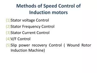
Contents • Overview of Three-Phase Induction Motor • Construction • Principle of Operation • Equivalent Circuit • Power Flow, Losses and Efficiency • Torque-Speed Characteristics • Speed Control • Overview of Single-Phase Induction Motor
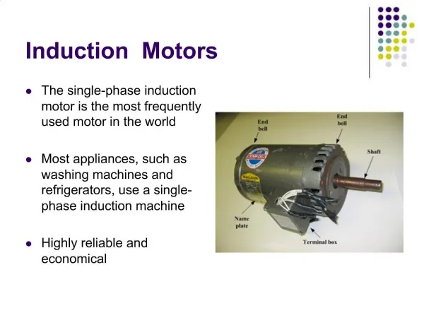
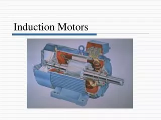
Overview of Three-Phase Induction Motor • Induction motors are used worldwide in many residential, commercial, industrial, and utility applications. • Induction Motors transform electrical energy into mechanical energy. • It can be part of a pump or fan, or connected to some other form of mechanical equipment such as a winder, conveyor, or mixer.
Introduction General aspects • A induction machine can be used as either a inductiongenerator or a induction motor. • Induction motors are popularly used in the industry • Focus on three-phase induction motor • Main features: cheap and low maintenance • Main disadvantages: speed control is not easy
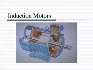
Construction • The three basic parts of an AC motor are the rotor, stator, and enclosure. • The stator and the rotor are electrical circuits that perform as electromagnets.
Construction (Stator construction) • The stator is the stationary electrical part of the motor. • The stator core of a National Electrical Manufacturers Association (NEMA) motor is made up of several hundred thin laminations. • Stator laminations are stacked together forming a hollow cylinder. Coils of insulated wire are inserted into slots of the stator core. • Electromagnetism is the principle behind motor operation. Each grouping of coils, together with the steel core it surrounds, form an electromagnet. The stator windings are connected directly to the power source. MZS FKEE, UMP
Construction (Rotor construction) • The rotor is the rotating part of the electromagnetic circuit. • It can be found in two types: • Squirrel cage • Wound rotor • However, the most common type of rotor is the “squirrel cage” rotor.
Construction (Rotor construction) • Induction motor types: • Squirrel cage type: • Rotor winding is composed of copper bars embedded in the rotor slots and shorted at both end by end rings • Simple, low cost, robust, low maintenance • Wound rotor type: • Rotor winding is wound by wires. The winding terminals can be connected to external circuits through slip rings and brushes. • Easy to control speed, more expensive.
Short circuits all rotor bars. /rotor winding Construction (Rotor construction) Wound Rotor Squirrel-Cage Rotor MZS FKEE, UMP
Stator Rotor Air gap Construction (Enclosure) • The enclosure consists of a frame (or yoke) and two end brackets (or bearing housings). The stator is mounted inside the frame. The rotor fits inside the stator with a slight air gap separating it from the stator. There is NO direct physical connection between the rotor and the stator. • The enclosure also protects the electrical and operating parts of the motor from harmful effects of the environment in which the motor operates. Bearings, mounted on the shaft, support the rotor and allow it to turn. A fan, also mounted on the shaft, is used on the motor shown below for cooling.
Rotating Magnetic Field • When a 3 phase stator winding is connected to a 3 phase voltage supply, 3 phase current will flow in the windings, which also will induced3 phase flux in the stator. • These flux will rotate at a speed called a Synchronous Speed, ns. The flux is called as Rotating magnetic Field • Synchronous speed: speed of rotating flux • Where; p = is the number of poles, and f = the frequency of supply
RMF(Rotating Magnetic Field) a Fc b’ 1.5 c’ Fa F t = t0= t4 F 1 Fa c Fc b 0.5 Fb a’ 0 Fb -0.5 t = t0= t4 -1 -1.5 -93 10 113 216 F Space angle () in degrees Fb Fc a Fb b’ a a c’ b’ b’ c’ c’ Fa c b c c F b b a’ Fc Fc a’ a’ Fb t = t2 t = t3 t = t1 F
MMF Due to ‘a’ phase current 1 Axis of phase a 0.8 t0 0.6 t01 0.4 0.2 Fa a’ a 0 a’ t12 -0.2 -0.4 -0.6 t2 -0.8 -1 -90 -40 10 60 110 160 210 260 Space angle (theta) in degrees
Currents in different phases of AC Machine t01 t12 Amp t1 t2 t3 t4 t0 time 1 Cycle
Slip Ring Rotor • The rotor contains windings similar to stator. • The connections from rotor are brought out using slip rings that • are rotating with the rotor and carbon brushes that are static.
Slip and Rotor Speed • Slip s • The rotor speed of an Induction machine is different from the speed of Rotating magnetic field. The % difference of the speed is called slip. • Where; ns = synchronous speed (rpm) nr = mechanical speed of rotor (rpm) • under normal operating conditions, s= 0.01 ~ 0.05, which is very small and the actual speed is very close to synchronous speed. • Note that : s is not negligible MZS FKEE, UMP
Slip and Rotor Speed • Rotor Speed • When the rotor move at rotor speed, nr (rps), the stator flux will circulate the rotor conductor at a speed of (ns-nr) per second. Hence, the frequency of the rotor is written as: • Where; s= slip f = supply frequency
Principle of Operation • Torque producing mechanism • When a 3 phase stator winding is connected to a 3 phase voltage supply, 3 phase current will flow in the windings, hence the stator is energized. • A rotating flux Φ is produced in the air gap. The flux Φ induces a voltage Ea in the rotor winding (like a transformer). • The induced voltage produces rotor current, if rotor circuit is closed. • The rotor current interacts with the flux Φ, producing torque. The rotor rotates in the direction of the rotating flux.
Direction of Rotor Rotates • Q: How to change the direction of • rotation? • • A: Change the phase sequence of the • power supply.
Equivalent Circuit of Induction Machines • Conventional equivalent circuit • Note: • Never use three-phase equivalent circuit. Always use per- phase equivalent circuit. • The equivalent circuit always bases on the Y connection regardless of the actual connection of the motor. • Induction machine equivalent circuit is very similar to the single-phase equivalent circuit of transformer. It is composed of stator circuit and rotor circuit
f f Equivalent Circuit of Induction Machines • Step1 Rotor winding is open (The rotor will not rotate) • Note: • the frequency of E2 is the same as that of E1 since the rotor is at standstill. At standstill s=1.
f fr Equivalent Circuit of Induction Machines • Step2 Rotor winding is shorted (Under normal operating conditions, the rotor winding is shorted. The slip is s) • Note: • the frequency of E2 is fr=sf because rotor is rotating.
Equivalent Circuit of Induction Machines • Step3 Eliminatef2 Keep the rotor current same:
Equivalent Circuit of Induction Machines • Step 4 Referred to the stator side • Note: • X’2 and R’2 will be given or measured. In practice, we do not have to calculate them from above equations. • Always refer the rotor side parameters to stator side. • Rcrepresents core loss, which is the core loss of stator side. MZS FKEE, UMP
Equivalent Circuit of Induction Machines • IEEE recommended equivalent circuit • Note: • Rc is omitted. The core loss is lumped with the rotational loss. MZS FKEE, UMP
I 1 Equivalent Circuit of Induction Machines • IEEE recommended equivalent circuit Note: can be separated into 2 PARTS • Purpose : • to obtain the developed mechanical MZS FKEE, UMP
Is1 Im1 IR1 Zs Vs1 Zm ZR Analysis of Induction Machines • For simplicity, let assume Is=I1 , IR=I2 (s=stator, R=rotor)
Is1 Im1 IR1 Zs Vs1 Zm ZR Analysis of Induction Machines Note : 1hp =746Watt
Pin (Motor) Pdeveloped Pmechanical Pconverted (Pm) Pin (Rotor) Pout, Po Pair Gap (Pag) Pin (Stator) Pstator copper loss, (Pscu) Protor copper loss (Prcu) Pwindage, friction, etc (P - Given) Pcore loss (Pc) Power Flow Diagram
Power Flow Diagram • Ratio: Ratio makes the analysis simpler to find the value of the particular power if we have another particular power. For example:
Torque-Equation • Torque, can be derived from power equation in term of mechanical power or electrical power.
Tmax Tm Tst s=1 ns smax smax is the slip for Tmax to occur Torque-Equation • Note that, Mechanical torque can written in terms of circuit parameters. This is determined by using approximation method Hence, Plot Tmvs s
Speed Control • There are 3 types of speed control of 3 phase induction machines • Varying rotor resistance • Varying supply voltage • Varying supply voltage and supply frequency
T R1<R2<R3 nr1< nr2< nr3 R1 R2 R3 T n nr3 nr2 nr1 ns~nNL Varying rotor resistance • For wound rotor only • Speed is decreasing • Constant maximum torque • The speedat which max torque occurs changes • Disadvantages: • large speed regulation • Power loss in Rext – reduce the efficiency
T V1 V decreasing V2 V1>V2 >V3 nr1> nr2 > nr3 V3 T n nr3 nr2 nr1 ns~nNL Varying supply voltage • Maximum torque changes • The speed which at max torque occurs is constant (at max torque, XR=RR/s • Relatively simple method – uses power electronics circuit for voltage controller • Suitable for fan type load • Disadvantages : • Large speed regulation since ~ ns
f decreasing T T n nr3 nr2 nr1 nNL1 nNL3 nNL2 Varying supply voltage and supply frequency • The best method since supply voltage and supply frequency is varied to keep V/f constant • Maintain speed regulation • uses power electronics circuit for frequency and voltage controller • Constant maximum torque