Download
1 / 64
640 likes | 780 Vues
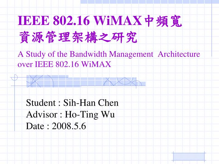
IEEE 802.16 WiMAX 中頻寬 資源管理架構之研究 A Study of the Bandwidth Management Architecture over IEEE 802.16 WiMAX. Student : Sih -Han Chen Advisor : Ho-Ting Wu Date : 2008.5.6. Outline. Introduction of IEEE802.16 and QoS Proposed QoS System Architecture Pairing Call Admission Control

E N D
IEEE 802.16 WiMAX中頻寬資源管理架構之研究A Study of the Bandwidth Management Architecture over IEEE 802.16 WiMAX Student : Sih-Han Chen Advisor : Ho-Ting Wu Date : 2008.5.6
Outline • Introduction of IEEE802.16 and QoS • Proposed QoS System Architecture • Pairing Call Admission Control • Bandwidth Borrowing on CAC level • Two Stage Bandwidth Allocation • Mandatory Packet Scheduling Algorithm • Performance Evaluation • Conclusion and Future Work
Worldwide Interoperability for Microwave Access(WiMAX) Bandwidth IEEE 802.15 IEEE 802.11 IEEE 802.16 3GPP 1 Gbps 802.15.3 High Speed Wireless PAN Wi-Fi 802.11n 100 Mbps WiMAX 802.16 (802.16-2004 & 802.16e) Wi-Fi 802.11a/b/g 10 Mbps 4G 3G 2.5G 1 Mbps 802.15.1 Bluetooth <1m 10m 100m Up to 50Km Up to 80Km PAN LAN MAN WAN PAN: Personal area networks MAN: Metropolitan area networks LAN: Local area networks Wide area networks
Defines multiple-access mechanism Functions : connection establishment connection maintenance Call admission control bandwidth request bandwidth allocation Packet shceduling MAC Common Part Sublayer MAC Common Part Sublayer (MPC)
Media Acces Control (MAC) • Connection orienteded • Service Flow(SF) • Connection ID (CID) • Channel access: • UL-MAP • Defines uplink channel access • Defines uplink data burst profiles • DL-MAP • Defines downlink data burst profiles • UL-MAP and DL-MAP are both transmitted in the beginning of each downlink subframe (FDD and TDD).
Bandwidth Request • SSs may request bandwidth in 3 ways: • Contention-based bandwidth requests (Broadcast Polling or Multicast Group Pollng) • Contention-free bandwidth requests (Unicast Polling) • Piggyback a BW request message on a data packet
BS grants/allocates bandwidth in one of two modes Grant Per Subscriber Station (GPSS) Grant Per Connection (GPC) Decision based on requestedBW, QoS parameters and available resources Grants are realized through the UL-MAP Bandwidth Allocation
Service Flow • The central concept of the MAC protocol • A service flow is a unidirectional flow of packets that is provided a particular QoS. • SS and BS provide this QoS according to the QoS parameter set. • Existing in both uplink and downlink and may exist without being activated. • Must have a 32bit SFID, besides admitted and active status also have a 16-bit CID
Attributes of a Service Flow Relationship of QoS Parameter Set • Service Flow ID • CID • ProvisionedQoSParamSet • AdmittedQoSParamSet • ActiveQoSParamSet • Authorization Module ProvisionedQoSParamSet (SFID) AdmittedQoSParamSet (SFID & CID) ActiveQoSParamSet (SFID & CID)
Dynamic Service Management • Dynamic Service Add (DSA) • Add a service flow • Dynamic Service Change (DSC) • Change an existing service flow • Dynamic Service Delete (DSD) • Delete a service flow
Outline • Introduction of IEEE802.16 QoS • Proposed QoS System Architecture • Pairing Call Admission Control • Bandwidth Borrowing on CAC level • Two Stage Bandwidth Allocation • Mandatory Packet Scheduling Algorithm • Performance Evaluation • Conclusion and Future Work
Proposed QoS Architecture BS SS Pair Call Admission Control Bandwidth Borrowing Agent Two Stage Bandwidth Allocation Downlink Packet Scheduler Connection Request Applications Core Network Connection Response Uplink Data Traffic Downlink Data Traffic Two Stage Bandwidth Allocation Down Stream (DL/UL MAP) Uplink Packet Scheduler Up Stream (Bandwidth Request)
Outline • Introduction of IEEE802.16 QoS • Proposed QoS System Architecture • Pairing Call Admission Control • Bandwidth Borrowing on CAC level • Two Stage Bandwidth Allocation • Mandatory Packet Scheduling Algorithm • Performance Evaluation • Conclusion and Future Work
Pairing Call Admission Control Each Pair Connection Request Bavailable>= Y Y Is UGS? Is nrtPS? Is rtPS? Is BE? Reject Call Accept Pair Call N Y N Enable Bandwidth Borrowing ? N Y Y Go Bandwidth Borrowing Agent N N Y
Outline • Introduction of IEEE802.16 QoS • Proposed QoS System Architecture • Pairing Call Admission Control • Bandwidth Borrowing on CAC level • Two Stage Bandwidth Allocation • Mandatory Packet Scheduling Algorithm • Performance Evaluation • Conclusion and Future Work
Bandwidth Borrowing Flow Chart Pair Connection Request from CAC Module Success Success Success Fail Fail Y Borrow from existing BE Cons Borrow from existing nrtPS Cons Borrow from existing rtPS Cons Borrow from existing rtPS Cons Borrow from existing nrtPS Cons Borrow from existing BE Cons Fail Is rtPS? Is UGS? Is nrtPS? Is BE? N Success Success Success Accept Accept Fail Fail Y Fail Reject Reject Y N Y Reject
Range of Bandwidth Reservation Rsv-nrtPS Rsv-rtPS Rsv-UGS Rsv-BE (Average+Min) /2 (Peak+Average) /2 Min/2 Average Rate Peak Rate 0 Min Rate Rsv-nrtPS Low Bound Rsv-BE Low Bound Rsv-rtPS Low Bound
Operation of Bandwidth Borrowing • Amount of bandwidth are needed to be borrowed from system • In system, the bandwidth can be borrowed from rtPS, nrtPS and BE individually
Operation of Bandwidth Borrowing • If , the bandwidth borrowing from each exiting BE connection: • Else, try to borrow bandwidth from nrtPS.
Operation of Bandwidth Borrowing • If , the bandwidth borrowing from each exiting nrtPSconnecion, after borrow from all : • Else, try to borrow bandwidth from rtPS.
Operation of Bandwidth Borrowing • If ,the bandwidth borrowing from each exiting rtPSconnecion, after borrow from all and and: • Else, Bandwidth Borrowing Fail ! Reject the connection request.
Outline • Introduction of IEEE802.16 QoS • Proposed QoS System Architecture • Pairing Call Admission Control • Bandwidth Borrowing on CAC level • Two Stage Bandwidth Allocation • Mandatory Packet Scheduling Algorithm • Performance Evaluation • Conclusion and Future Work
Two Stage Bandwidth Allocation • Stage One: • Give the guarantee reserved bandwidth at most. • Obtain fairness, guarantee each connection shares the bandwidth • Stage Two : • Allocate the remaining bandwidth. • Partial fairness. Use weighting ( i.e. rtPS:nrtPS:BE = 2:1:1 ) to share the bandwidth.
Outline • Introduction of IEEE802.16 QoS • Proposed QoS System Architecture • Pairing Call Admission Control • Bandwidth Borrowing on CAC level • Two Stage Bandwidth Allocation • Mandatory Packet Scheduling Algorithm • Performance Evaluatioin • Conclusion and Future Work
Outline • Introduction of IEEE802.16 QoS • Proposed QoS System Architecture • Pairing Call Admission Control • Bandwidth Borrowing on CAC level • Two Stage Bandwidth Allocation • Mandatory Packet Scheduling Algorithm • Performance Evaluation • Conclusion and Future Work
System Model of Simulation Experiment Note : We assume that only SS can send the connection request to BS actively
Performance Metric • Call Blocking Probability : • Packet Drop Rate : • Packet Delay :
Definition of Pairing CAC • Accepted : • Reject :
Definition of NonPairing CAC Accept Call • Round Trip Time: • The duration time between admitting Uplink Connection Reqest and BS send out the Downlink Connection Request.
Definition of NonPairing CAC • Default RTT of DL connection request : 0.5 seconds • Accepted : • First Type of Connection Fail : • Second Type of Connection Fail :
Call Blocking ProbabilityNonPairing CAC vs Pairing CAC RTT = 0.5s
Call Blocking Probability- Pair vsNonPair (RTT=0.5) UGS rtPS nrtPS BE
Pairing vsNonPairing (RTT= 0.5s, 5s, 10s) UGS rtPS nrtPS BE
In Pairing CAC ModeNon Bandwidth Borrowing (NonBB)vsBandwidth Borrowing (BB)
Call Blocking ProbabilityNonBBvs BB NonBB mode BB mode