Download
1 / 21
210 likes | 213 Vues
This study explores the use of substituted carbazole compounds in the emitting layer of organic light emitting diodes (OLEDs) to achieve highly efficient pure blue light emission. Two new carbazole compounds, PMC and DEC, are investigated in both neat film and doped film configurations. The results show that the neat film of DEC achieves a higher external quantum efficiency of 1.5%, while the neat film of PMC produces a brighter saturated blue light. Through further investigation of emitting mixtures, the potential of achieving even higher efficiencies in blue OLEDs is explored.

E N D
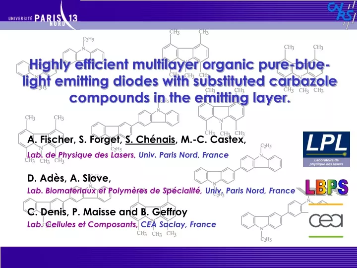
Highly efficient multilayer organic pure-blue-light emitting diodes with substituted carbazole compounds in the emitting layer. A. Fischer, S. Forget, S. Chénais, M.-C. Castex, Lab. de Physique des Lasers, Univ. Paris Nord, France D. Adès, A. Siove, Lab. Biomateriaux et Polymères de Spécialité, Univ. Paris Nord, France LBPS C. Denis, P. Maisse and B. Geffroy Lab. Cellules et Composants, CEA Saclay, France
Outline • Introduction : why BLUE oleds ? • Two new carbazolic compounds : PMC (Pentamethylcarbazole) and DEC (Dimer of N-ethylcarbazole) • Devices using neat films of PMC and DEC in single layer and multilayer structures • Devices using doped films of PMC:DPVBi and DEC:DPVBi • Conclusion
Introduction Organic Light Emitting Diodes : • Ultrathin light sources, lightweight • High brightness and viewing angle > 160° • Low drive voltage (3-10 V) and low power consumption • Extremely rich diversity of materials : All visible colors available (≠ inorganic LEDs), including saturated colors • Potentially flexible • Long lifetimes (> 20 000 h reported) • Low cost potential for mass production • Applications : flat-panel RGB DISPLAYS, solid-state lighting,...
Why BLUE ? Why Blue OLEDs with high efficiencies are needed ? • different approaches for multi-color emission : Color changing media RGB emitters White emitters + Filters + : homogeneous aging - : not efficient (filters) needs efficient blue emitters to achieve bright white + : homogeneous aging - : not efficient (photoconversion) + : power efficient, mature - : different aging and optimization needs efficient blue emitters (efficient R,G already exist) needs efficient blue emitters
OLEDs materials CIE 1931 • Requirements for an efficient blue material : • Chemical stability and Electrochemical stability • High Tg • High quantum yield of photoluminescence in the solid state • Chromaticity coordinates approaching the spectrum locus(saturated color) • Active research for new blue-emitting organic materials • (both fluorescent and phosphorescent)
OLEDs materials PMC DEC • - Blue emitters: Carbazole-substituted Distyrylarylenes (DSA) • - Hole Transport materials : PVK • - Host material for triplet emitters: CBP • Carbazolic derivatives Carbazole unit : Already used as… new • Chemically and thermally stable (up to 430 °C) • Tg = 75°C • Polaronic transport levels measured by cyclic voltammetry (eV) : Vacuum level Lowest Unoccupied Molecular Orbital 2.5 2.8 5.6 penta-methyl carbazole Highest Occupied Molecular Orbital 5.9 Dimer of N-Ethyl carbazole DEC PMC
OLEDs structures • 1st DEC-based diode : single layer D. Romero, A. Siove et al., Adv. Mater.9, 1158 (1997) V Al • Drawbacks: • Low ext. quantum efficiency ext. = 7.10-2 % • High operating voltage (20 V), crystallization during operation (short-circuit) DEC ITO h Bad performance due to recombination and quenching of excitons at Al/DEC interface, poor charge injection • This work : Use of DEC (and PMC) in a multilayer OLED structure with both neat films and doped films configurations: efficient deep-blue organic emitter
Device a : OLED with NEAT film of DEC CuPc NPB 2.5 electrons 2.9 2.4 2.4 2.4 LUMO Cathode 3.0 3.6 holes 4.7 HIL HTL Anode ETL HBL 5.3 5.4 HOMO 5.6 5.7 6.1 NPB 50 nm BCP 10nm Alq3 10nm LiF / Al 1.2 / 100nm DEC 50 nm ITO 100-150nm CuPc 10nm
Device a : OLED with neat film of DEC Main recombination zone 2.5 electrons 2.9 2.4 2.4 2.4 LUMO Cathode 3.0 3.6 holes 4.7 HIL HTL Anode ETL HBL 5.3 5.4 HOMO 5.6 5.7 6.1 NPB 50 nm BCP 10nm Alq3 10nm LiF / Al 1.2 / 100nm DEC 50 nm ITO 100-150nm CuPc 10nm ηext = 1.5 % (optical design not optimized)
Device a : OLED with neat film of PMC NPB electrons 2.8 2.9 2.4 2.4 LUMO Cathode 3.0 3.6 PMC OLED holes 4.7 HIL HTL ETL Anode 5.3 HBL 5.4 5.7 HOMO 5.9 6.1 NPB 50 nm BCP 10nm Alq3 10nm LiF / Al 1.2 / 100nm PMC 50 nm ITO 100-150nm CuPc 10nm → attributed to bad electron transport properties of PMC / electron barrier of BCP ηext = 0.6 %
Device a : OLED with neat film of PMC Main recombination zone electrons 2.8 2.9 2.4 2.4 LUMO Cathode 3.0 3.6 PMC OLED holes 4.7 HIL HTL ETL Anode 5.3 HBL 5.4 5.7 HOMO 5.9 6.1 NPB 50 nm BCP 10nm Alq3 10nm LiF / Al 1.2 / 100nm PMC 50 nm ITO 100-150nm CuPc 10nm → attributed to bad electron transport properties of PMC / electron barrier of BCP ηext = 0.6 %
Device a (neat films) : Experimental results DEC PMC a Chromaticity coordinates • Electroluminescence spectra Aggregates, excimers ? PMC : CIE x = 0.153 ; y = 0.100 DEC : CIE x = 0.192 ; y = 0.209 Ext. Quantum efficiency : ηext = 0.6 % (PMC) ηext = 1.5 % (DEC) → Bright saturated blue With PMC, but modest efficiency Brightness L = 236 cd/m2 @ 60 mA/cm2 (PMC) Luminous efficiencyηpower = 0.2 lm/W (PMC)
Investigating emitting mixtures (« doping ») The role of emitting mixtures (or « doping » but not in the electrical sense !) • « energy transfer » doping = diluting a low-gap guest material inside a wide-gap host : Förster (and Dexter) energy transfers possible → Very efficient mechanism but not useful for blue emitters guest host • other types of doping : the dopant « impurities » can enhance exciton recombination by trapping charge carriers (and diffusing excitons) Barrier for electrons + trap for holes = improved recombination rate Ex : guest host
Device b : OLEDs with DPVBi doped with PMC (DEC) LiF 1.2nm/Al 100nm Alq 10nm 3 PMC DPVBi (PMC or DEC) 50nm (b) NPB 50nm CuPc 10nm ITO glass DEC 5% wt. + or 2% wt. DPVBi 4,4’-bis(2,2’-diphenylvinyl)-1,1’-biphenyl Vacuum level • Doping by coevaporation from 2 resistively heated cells Lowest Unoccupied Molecular Orbital 2.5 2.8 2.8 5.6 Highest Occupied Molecular Orbital 5.9 5.9 DEC DPVBI PMC
OLEDs with DPVBi doped with DEC 2% DEC 2.5 electrons 2.9 2.4 LUMO 3.0 2.8 Cathode 3.6 holes DPVBi 4.7 HIL HTL Anode 5.3 5.6 ETL 5.4 HOMO 5.7 5.9 Alq3 10nm LiF / Al 1.2 / 100nm NPB 50 nm DEC:DPVBi 50 nm ITO 100-150nm CuPc 10nm
OLEDs with DPVBi doped with DEC Recombination zone 2% DEC 2.5 electrons 2.9 2.4 LUMO 3.0 2.8 Cathode 3.6 holes DPVBi 4.7 HIL HTL Anode 5.3 5.6 ETL 5.4 HOMO 5.9 5.7 Alq3 10nm LiF / Al 1.2 / 100nm NPB 50 nm DEC:DPVBi 50 nm ITO 100-150nm CuPc 10nm ηext = 3.3 %
OLEDs with DPVBi doped with PMC 5% PMC Recombination zone electrons 2.9 2.4 LUMO 3.0 2.8 Cathode 3.6 holes DPVBi 4.7 HIL HTL Anode 5.3 ETL 5.4 HOMO 5.7 5.9 Alq3 10nm LiF / Al 1.2 / 100nm NPB 50 nm PMC:DPVBi 50 nm ITO 100-150nm CuPc 10nm ηext = 2.8 %
Comparison point : OLEDs with DPVBi ALONE Recombination zone electrons 2.9 2.4 LUMO 3.0 2.8 Cathode 3.6 holes DPVBi 4.7 HIL HTL Anode 5.3 ETL 5.4 HOMO 5.7 5.9 Alq3 10nm LiF / Al 1.2 / 100nm NPB 50 nm PMC:DPVBi 50 nm ITO 100-150nm CuPc 10nm ηext = 2.7 %
Device b (doping) : SUMMARY DEC:DPVBi PMC:DPVBi DPVBi ► All spectra similar to DPVBi and NPB : which material is emitting light ? ►no shoulder in DEC spectra : suppression of aggregates by dilution
Summary • We demonstrated state-of-the-art external quantum efficiency of 3.3% with a deep-blue OLED (CIE x = 0.15 ; y = 0.17) using a DEC:DPVBi emitting mixture Close to the max 5% = 25% (singlet/triplet ratio) x 20% (extraction efficiency) • Efficiency of the doping approach : DEC:DPVBi better than DPVBi alone (or DPVBI:PMC) : attributed to enhanced trapping of charged carriers • PMC exhibits the most saturated color (x = 0.15 ; y= 0.10) : better efficiency would be achievable with a different design while keeping the CIE coordinates (in progress)