Download
1 / 15
150 likes | 296 Vues
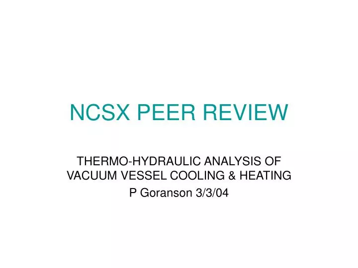
NCSX PEER REVIEW. THERMO-HYDRAULIC ANALYSIS OF VACUUM VESSEL COOLING & HEATING P Goranson 3/3/04. GOAL. DETERMINE SIZE AND NUMBER OF COOLANT LINES THERMO-HYDRAULIC PARAMETERS VIABILITY OF DESIGN. REQUIREMENTS/CRITERIA. VV BAKED AT 350 C MAINTAINED 20-40 C BEFORE AND AFTER OPERATION

E N D
NCSX PEERREVIEW THERMO-HYDRAULIC ANALYSIS OF VACUUM VESSEL COOLING & HEATING P Goranson 3/3/04
GOAL • DETERMINE SIZE AND NUMBER OF COOLANT LINES • THERMO-HYDRAULIC PARAMETERS • VIABILITY OF DESIGN
REQUIREMENTS/CRITERIA • VV BAKED AT 350 C • MAINTAINED 20-40 C BEFORE AND AFTER OPERATION • 15 MINUTE REP RATE DURING OPERATION • FULL UPGRADE HEATING – 12 mw FOR 1.2 S
ASSUMPTIONS • Heat Input and Output Based on DAC NCSX-CALC-121-03-00_dA, Heat Balance of the NCSX Vacuum Vessel During Operation and Bakeout. - 17 kW during bakeout - 16 kW average during cooling • VV temp rise 11.7 K during shot, evenly distributed. • Helium coolant
CONFIGURATION • Dual tubes on common brackets - Grafoil gaskets - copper alloy pads • Increases heat transfer area • Decreases diameter - easier bending - smaller envelope • 16 pairs on half period (192 total tubes) Tracing Mount Detail Typical Field Period
THERMO-HYDRAULIC CALCULATIONS • EXCEL Spreadsheet • Standard Incompressible Fluid Flow Equations • Inputs - tube dia • flow rate • pressure • vessel temperature • Outputs • flow parameters • film coef. • temperature changes, etc.
HELIUM PROPERTIES 20 atmosphere Helium at 20 C • spec ht(J/g-K) 5.19 • density(g/cm^3) 0.0032 • cond.(w/cm-K) 0.00154 • dyn visc.(g/cm-s) 1.99E-04 • diffusivity (cm^2/s) 9.27E-02 • Prandtl 0.67 • He kin. visc. (cm^2/s) 6.22E-02 20 atmosphere Helium at 350 C • spec ht(J/g-K) 5.20 • density(g/cm^3) 0.0020 • cond.(w/cm-K) 0.0034 • dyn visc.(g/cm-s) 3.96E-04 • diffusivity (cm^2/s) 1.52E-01 • Prandtl 0.65 • He kin. visc. (cm^2/s) 9.83E-02
INCONEL PROPERTIES • spec ht(J/g-K) 0.42 • density(g/cm^3) 8.03 • cond.(w/cm-K) 0.121 • diffusivity (cm^2/s) 0.036
RESULTS - ROOM TEMP OPERATION Results for 5/16” OD tube, 0.028” wall Helium pressure 20 atmos
Pressure Film coef Item Model Length Length Drop Mass flow (w/cm^2-K) Temp drop Bulk Exit vel Inlet vel No No (in) (cm) (atmos) (g/s) Re f h bulk dT(K) temp(C) (m/s) (m/s) 1 SE123-011.PRT 180.6 458.8 0.099 1.3 6588 0.035 0.117 15.9 351.1 19.1 19.5 2 SE123-012.PRT 173.8 441.4 0.099 1.4 6716 0.035 0.119 15.2 351.8 19.5 19.9 3 SE123-013.PRT 171.5 435.7 0.099 1.4 6760 0.035 0.120 15.0 352.0 19.6 20.1 4 SE123-014.PRT 191.6 486.8 0.099 1.3 6395 0.035 0.114 16.9 350.1 18.5 19.0 5 SE123-015.PRT 190.6 484.2 0.099 1.3 6413 0.035 0.115 16.8 350.2 18.5 19.0 6 SE123-016.PRT 194.7 494.7 0.099 1.3 6344 0.035 0.114 17.2 349.8 18.3 18.8 7 SE123-017.PRT 207.5 527.1 0.099 1.2 6146 0.036 0.111 18.5 348.5 17.7 18.2 8 SE123-018.PRT 215.9 548.5 0.099 1.2 6025 0.036 0.109 19.3 347.7 17.3 17.8 9 SE123-019.PRT 245.3 623.0 0.099 1.1 5653 0.036 0.104 22.2 344.8 16.1 16.7 10 SE123-020.PRT 246.2 625.2 0.099 1.1 5643 0.036 0.104 22.3 344.7 16.1 16.6 11 SE123-021.PRT 256.1 650.5 0.099 1.1 5532 0.037 0.102 23.3 343.7 15.7 16.3 12 SE123-022.PRT 232.1 589.6 0.099 1.2 5811 0.036 0.106 20.9 346.1 16.6 17.2 13 SE123-023.PRT 215.6 547.5 0.099 1.2 6030 0.036 0.109 19.3 347.7 17.3 17.8 14 SE123-024.PRT 251.7 639.3 0.099 1.1 5581 0.037 0.103 22.9 344.1 15.9 16.5 15 SE123-025.PRT 262.2 666.1 0.099 1.1 5467 0.037 0.101 23.9 343.1 15.5 16.1 16 SE123-026.PRT 236.2 600.0 0.099 1.2 5760 0.036 0.105 21.3 345.7 16.4 17.0 total (m) 1058.2 total 19.6 av 0.110 19.4 av.(m) 5.51 av. 1.23 RESULTS – BAKEOUT Results for 5/16” OD tube, 0.028” wall Helium pressure 20 atmos
Coolant tube THERMAL RESPONSE ANALYSIS Hand calculation using finite slab, cooled at edges • L = 4 inches • t = 0.375 inches • Constant heat transfer coef. at tube( from chart) • Constant starting temperature across plate t 2L
HELIUM COOLED VESSEL RATCHETING TEMPERATURE AS A FUNCTION OF COOL DOWN TIME 60 55 50 45 40 35 30 25 20 0 10 20 30 40 50 60 70 80 90 100 110 120 130 140 150 TIME (MIN) VESSEL RATCHETING Vessel ratchets to 40 C at steady state End of cool down
CONCLUSIONS • 1/4” Tubes give inadequate mass flow • 10 Atmos Helium inadequate - 20 Atmos Helium required • 5/16” Tubes permit baking and cooling with large margin - small pressure drop - moderate flow velocity - moderate temperature drops • Vessel does not return to start temperature - Ratchets beyond 40 C with present bracket spacing
CAVEATS • Additional ports have been added. • Tubes must be reconfigured, lengths changed somewhat • 3-D analysis of brackets indicates tube spacing or operation must change if GRD is to be accommodated.