Download
1 / 60
610 likes | 702 Vues
Vanderbilt FRR Presentation. Tuesday April 5 th , 2011. Presentation Contents. Motor choice Rocket flight stability in static margin diagram Thrust to weight motor selection in flight simulation Rail exit velocity Parachute sizes and descent rates Test plans and procedures

E N D
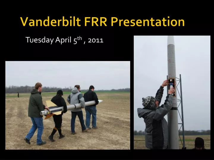
Vanderbilt FRR Presentation Tuesday April 5th , 2011
Presentation Contents • Motor choice • Rocket flight stability in static margin diagram • Thrust to weight motor selection in flight simulation • Rail exit velocity • Parachute sizes and descent rates • Test plans and procedures • Dual deployment avionics test • Ejection charge amount test • Full scale flight test • Payload integration feasibility • Educational Engagement Plan and Status
Construction Highlights • Giant Leap “Magnaframe” airframe • 1/8” Nomex honeycomb fins reinforced with Carbon fiber • ½” plywood centering rings and bulkheads • West System Epoxy and ¼”-20 hardware in load-bearing components
Rocket Construction • Pre-ejection retention : 4 [#4-40] nylon screws Payload/avionics bay • 1” plywood caps • Two ¼” threaded rod lengths • Two ¼” U-bolts at each end • Coupler tube / payloadbay and avionics baymounted with six ¼”-20 bolts • Three ½” plywood centering rings
Motor Choice: M650 W • Diameter: 75 mm • Average Thrust: 656 N • Max. Thrust: 1475 N • Total Impulses: 5964 Ns • Burn Time: 9.1 seconds
Deployment Testing Summary • Charge sizing: 2.1 grams (aft event) 3.2 grams (forward event) • The charges proved sufficient to shear the four #4-40 nylon screws and cause clean separation of the rocket sections • The tests were performed with shock cords and quicklinks, but NO parachutes
Drogue (Apogee) 2.1g MAWD 1 MAIN @700 ft 3.2 g powder MAWD 2 (Auxiliary) Drogue (Apogee) 2.1g Main @ 500 ft 3.2g powder Deployment Testing Summary *Four nylon 4-40 screws were used to harness each of the sections
Full scale launch summary • We conducted our full scale launch on Saturday March 26, 2011 • Ground conditions were dry • It was a cloudy day with 10-12 mph winds
Full scale launch flight description • We did not add ballast because of wind • The rocket took off and cleared the launch pad reasonably well • High winds caused windcocking soon after takeoff
Deployment disaster • Both charges fired • Drogue deployed, but did not unfurl • Main did not deploy • Rocket body and fins were heavily damaged, but electronics and payload were intact
Six main issues were addressed by the full scale flight: • Rocket preparation time and team coordination skills. (total prep time: <3 hrs)
Six main issues were addressed by the full scale flight: • Cryogen compartment loading, safe handling at the launch pad, and time required. (total time: 15 min)
Six main issues were addressed by the full scale flight: • Flight according to high power rocketry design principles: thrust-to-weight ratio, stability margin, proper harnessing of payload and rocket constituent parts.
Six main issues were addressed by the full scale flight: • Successful recovery of the rocket through optimal deployment of the drogue and main parachutes.
Six main issues were addressed by the full scale flight: • Payload design and successful performance to achieve science objectives
Six main issues were addressed by the full scale flight: • Suitability of long burn M650 motor for achieving one-mile altitude and science objectives
Flight Simulation Summary *All simulations were based on a launch weight of 51.73 lbs (23.46 kg)
Drogue (Apogee) 4.0 g 3 Pins #4-40 MAWD 1 MAIN @900 ft 5.0 g powder 4 Pins #4-40 MAWD 2 (Auxiliary) Drogue (Apogee) 5.0 g Main @ 700 ft 6.0 g powder Rocket Modifications for USLI • Use a factor of safety of 2.0 in deployment charge sizing • Conduct three high quality deployment tests
Rocket Modifications for USLI • Use a 2 lb ballast in the tail section for USLI launch (improved stability margin) • Fill up the conical termination of the nose cone with expanding foam to prevent parachute from being snugly lodged in the nose cone. • Deploy main parachute at 900 ft, to allow for sufficient time for main deployment
Current Status • The team works on a flexible platform to guard against rocket failures like this: we have an extra tail section ready • The team is rebuilding the payload section • Next flight options: • Manchester HARA, Saturday April 9th (Darryl Hankes L3 assisting) • Elizabethtown , Sunday April 10th (Darryl Hankes L3 assisting)
Payload Design Overview • Forward payload [rocket body]: • 500 mL cryogenic container • Solenoid valve and delivery lines • Data Acquisition Electronics • Proper Support and insulation • Aft payload [rocket exhaust]: • Thermoelectric engine with cryogen injectors • Optimized for 75 mm Aerotech M650W
Revisions in Payload Integration • Impossible to insert cryogen tank during rocket assembly while horizontal • Causes unacceptable leak and exposure to LN2 • Solution: Create access hatch in rocket / payload bay to allow integration at the launch pad • Cryogen delivery lines changed to SS tubing within PVC conduit for ease of assembly and insulation
Access Hatch Details / Construction • 6.5” x 14” (arc length by height) • Inner door given ¾” margin on each side for attachment • The door is secured to the rocket with big plastic rivets and further held in place with gorilla tape
Cryogen Delivery Lines & Assembly • 5/16” ID Stainless Steel tube • Allows LN2 to travel to injector without unacceptable loss at 50 psi • Verified through experimental testing • ½” PVC conduit w/aluminum plugs • Plugs secure SS tube in center of conduit • Conduit filled with expanding foam • 1” PVC conduit within rocket • Smaller conduit slides in for ease of installation • Aluminum bracket in motor mount area provides retention of cryogen delivery lines
Cryogen Tank Overview • Custom modified liquid nitrogen tank with cryogen rated solenoid valve installed • Upright tank orientation • 50 psi valve installed to enhance LN2 delivery through cryogen lines • Burst pressure of tank: ~2700 psi
Cryogen Line Testing • Simulated 3D TEG payload with high-speed VASA fan • 6 ft Stainless steel delivery line • Testing with new 50 psi vent valve installed on tank • Used G-trigger circuitry to ensure proper electronic actuation
Cryogenic Testing Summary • Pure liquid nitrogen available within 2.5” of launch • Temperature of liquid nitrogen ~ -125C • Optimal value for cryogenic cooling (and thus parity) is achieved at ~7.5 seconds
Payload Integration Two bulkheads with cutouts for the cryogen tank are secured to threaded rods with nuts and further epoxied to the inside of the body tube
Payload Integration Quick assembly/disassembly using aluminum brackets bolted and epoxied to bulkheads Aluminum brackets
Payload Integration electric lines for solenoid ½” conduit with SS delivery line • Area above and below the tank is filled with “impact” memory foam • The tank is well secured both axially and radially
Cryogen Bay Assembly Cryogen Tank Vents Payload Electronics
Location in rocket Payload Bay
Cryogen Fill Procedure [revisited] • Determined that filling during rocket assembly was not the best solution. • Better solution: Fill at the launch pad after lifting rocket to ~45 ° angle, theninstall the cryogen tank and secure the door • Tank can be filled directly, eliminating spills and ensuring a full tank • Pre-cooling lines will be performed using secondary cryogen tank with hand valve • After pre-cool, the flight-ready tank will be installed
Aft Payload and Injection • Aft payload machined in-house from aluminum • Welded to motor retaining cap for rocket attachment • Injector constructed from slotted stainless steel, similar to 3-D experiments • 2 TEGs: one cooled, one uncooled comparator 7 injection points located between heat sink fins for optimal cooling “Y” shaped cryogen injector
Design Highlights • Cryogen delivery on launch detect • Vent valve changed to vent at 50 psi, and keep chamber at 50 psi • 5/16th ID stainless steel cryogen delivery line with foam insulation to achieve optimal cryogen transfer and TEG cooling in the ideal rocket flight window • Solenoid valve now opens for a 13 sec interval, most suitable for gathering experimental data. • Cryogen container installed into rocket at launch pad through safe payload bay door • Manual cryogen injection prior to launch possible to pre-cool lines if desired
Full Scale Launch The full scale launch demonstrated a 100% return on the team’s science objectives and a clear validation of its original hypothesis that low altitude rocket flight can be used to simulate cruising airplane flight conditions
Payload Expectations • Cryogen injection should occur with detection of rocket launch • Cryogen should be delivered within a maximum delay of two seconds from detection of rocket launch • Fin surface should be cooled by 35C equivalent to achieve parity with C130 flight, and 75C equivalent to achieve parity with B747 flight • Thermoelectric generator location on the TEG engine should be such that a maximum temperature of 260 °C (533K) be realized on the hot side • There should be no thermal interface breakdown with the use of high temperature thermal interface material. • Location of thermocouples on the TEG should be optimized for best estimation of device average temp.
Cooling Results *Cooling effects seen within 0.5 seconds
Payload Results: Cryogen Data Max power attained of 17 Watts for ΔT = 275C
130 m/s For a seven second period, parity can be found between rocket and airplane flight!
Max. efficiencies were achieved Carnot Seebeck
Payload Modifications for USLI • Set up additional TEG for power comparator studies • Set TEGs 1” fore (towards motor) of the current location to minimize Th to less than 300 °C • Set up a cold side thermocouple on comparator TEG to establish temperature rise in the absence of cryogenic cooling • Use longer time scale thermocouple (C03 K) for hot side temperature measurement to establish a more realistic temperature rise through the TEG device • Locate thermocouples at 0.6 L to better approximate the average temperature of the TEG device.
Finance Management • Current amount spent:~$11,150 • ~$3,850.00 remains before we exceed our spending limit • Anticipated future costs include: • Expenses associated with travelling to USLI launch including food, transportation, lodging ~$1400 • Replacement rocket parts ~$1000 • Contingency fund ~$1000 • Budgeting strategy: frugality. Spend conservatively and reuse available parts wherever possible