Download
1 / 18
190 likes | 342 Vues
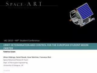
ESMO European Student Moon Orbiter and the EME Ham-Stations partecipation in the Bistatic RADAR Experiment. Piero Tognolatti, I Ø KPT Faculty of Engineering, University of L’Aquila, Italy (*) Email: i0kpt@amsat.org or p.tognolatti@ieee.org.

E N D
ESMO European Student Moon Orbiter and the EME Ham-Stations partecipation in the Bistatic RADAR Experiment Piero Tognolatti, IØKPT Faculty of Engineering, University of L’Aquila, Italy (*) Email: i0kpt@amsat.org or p.tognolatti@ieee.org (*) University Amateur-Radio Club Station callsign is IZ6BAJ
Outline • A short description of ESMO mission • Microwave Radiometer and its role as scientific payload • How Amateur-Radio community can contribute to scientific experiments involving Microwave Radiometer
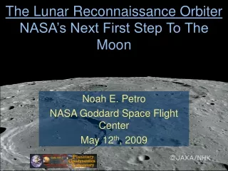
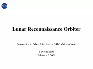
ESMO Mission In March 2006, the Education Department of the European Space Agency approved the European Student Moon Orbiter (ESMO) mission proposed by the Student Space Exploration & Technology Initiative (SSETI) association for a “Phase A” Feasibility Study. ESMO will be the third mission to be designed, built and operated by European students and would join many other contemporary missions to the Moon such as ESA’s SMART-1, the Chinese Chang’e-1, the Indian Chandrayaan, JAXA’s SELENE and Lunar-A, and NASA’s Lunar Reconnaissance Orbiter. “Phase B” is now going to start. • Italy has taken part in the project with: • Università di Roma “La Sapienza” • Università di L’Aquila • Politecnico di Milano • Università di Napoli “Federico II”
ESMO objectives The ESMO mission objectives are summarised as follows: • Education: prepare students for careers in future projects of the European space exploration and space science programmes by providing valuable hands-on experience on a relevant & demanding project • Outreach: acquire images of the Moon and transmit them back to Earth for public relations and education outreach purposes • Science: perform new scientific measurements relevant to lunar science & the future human exploration of the Moon, in complement with past, present and future lunar missions • Engineering: provide flight demonstration of innovative space technologies developed under university research activities
ESMO facts The ESMO spacecraft would be launched in 2011 as an auxiliary payload into a highly elliptical, low inclination Geostationary Transfer Orbit (GTO) on the new Arianespace Support for Auxiliary Payloads (ASAP) by either Ariane 5 or Soyuz from Kourou. From GTO, the 200 kg spacecraft would use its on-board propulsion system for lunar transfer, lunar orbit insertion and orbit transfer to its final low altitude polar orbit around the Moon. A 10 kg miniaturised suite of scientific instruments (also to be provided by student teams) would perform measurements during the lunar transfer and lunar orbit phases over the period of a few months. The core payload is a high-resolution narrow angle CCD camera for optical imaging of lunar surface characteristics Optional payload items being considered include a Microwave Radiometer, proposed by Universities of Rome “La Sapienza” and L’Aquila, Italy
Microwave brightness temperature image of the moon at 5.7 GHz Optical image from the earth Dark crater Shadowed regions Moon surface Wu Ji (Earth Syst. Sci. Dec. 2004) Wu Ji (Earth Syst. Sci. Dec. 2004) Why a Microwave Radiometer • Global mapping of the surface and sub-surface temperature. • Global mapping of the lunar microwave emissivity. • Estimate of the lunar soil thickness and properties. • Estimate of the lunar sub-surface thermal prperties. Proposed F=3 GHz & 10 GHz H=~200 km z Tb z=0 ε2,T2 d Moon soil z=-d ε3,T3 Rock
Corrugated horn @ 10 GHz Short Back-Fire @ 3 GHz 2λ=20 cm λ/2=5 cm Performances of proposed antennas Computed by Method of Moments (FEKO suite)
Another mode of operation …… • We have just seen that a microwave radiometer measures thermal (spontaneous) microwave noise emission from the Moon, gathering data on temperature vs. depth and emissivity. • We will now see how to use a microwave radiometer as a radar receiver in a so called “Bistatic Radar” system. • Radar transmitter(s) will be sited on the Earth and will be run by Ham-radio operators!
RADIOMETER Mode This is the usual mode of operation of a spaceborne radiometer! Brightness temperature Tb is measured at each orbit position
Incoherent RX, with AM demod., wide RF bandwidth (e.g 50 MHz), variable post-detector integration-time (e.g. 1s & 0.1ms) BISTATIC RADAR Mode (a) Perpendicular Incidence ESMO measures specular reflection Modulated signal One or more EME Ham stations “flood” the Moon at 10 GHz Do usual EME QSO’s disturb RADIOMETER mode of ESMO? EME activity is almost only on weekends, thus any impairment will be limited. Moreover ESMO radiometer could have a band switching capability, to go off ham-band.
BISTATIC RADAR Mode (b) Oblique Incidence ESMO measures specular reflection
Is it possible to measure the Brewster Angle ? (A reflection null for V-pol. Waves) • Can we observe Brewster Angle phenomenum? (˜60°) • Radiometer antenna is nadir-looking, so it has low gain for both direct and reflected EME signals. • Poor ESMO antenna-gain discrimination between reflected and direct EME signals. • At 10 GHz Brewster angle can be observed only on very smooth surfaces. • TX station has to control its linear polarization (spinning polarization may be an approach) • … soon we will see some solutions … • (*) Tyler G. L. Brewster angle of the lunar crust. Nature, 219, 1243–1244, 1968 describes measurements at 136 MHz made by Explorer 35 i=30° i=60° 39 dB 18 dB ESMO radiometer antenna pattern i
A quick view to Power Budget Let’s assume: • “Total Power“ radiometer • B = 50 MHz (equivalent noise bandwidth) = 1 s (integration time) • Tsys = Tant + Trec = 300K + 50K = 350 K (RX NF=0.7 dB) • Radiometric resolution: DT=0.05 K • Antenna gain: 16 dBi RADIOMETER Mode (no Hams flooding of the Moon) It can be easily seen that: • Noise power input to radiometer is: K Tsys B = -126.2 dBW • With proper calibration, the radiometer measures a brightness temperature: Tb = 300 K
PASSIVE RADAR Mode (with Ham flooding the Moon) - specular reflection considered - Noise power input to radiometer is now: K Tsys B + DP = (-126.2 dBW) + (-142 dBW) According to the calibration scale we have seen, DP produces an increase of 9.1 K in radiometer output. This increase is well large with respect to radiometric resolution, which is 0.05 K DP is estimated assuming a single EME station with: • EIRP TX : 77 dBW (e.g. 7 meter dish, TX 150 W, as for IQ4DF in Bagnara, Italy ) • R= 370 000 km F=10 GHz • Surface Moon reflectivity: -12 dB (typical value)
Example of High-EIRP EME station Bagnara di Romagna, Italy IQ4DF IQ4DF Thanks to Vico, I4ZAU
We can also increase the effective EIRP by involving more than a single high-power EME station. When a plurality of station are involved, their messages must be identical (except for callsign!) and synchronized (e.g using GPS time and their relative positions with respect to Moon). We can exploit a coherent approach, which gives us some process gain. As before, EME station radiates an amplitude-modulated signal (e.g. Morse). ESMO radio-meter, properly reconfigured, will sample at a convenient rate the received signal amplitude. Samples sequence will then be sent to Earth (by ESMO downlink facility), where the involved EME station will cross-correlate it with a stored copy of transmitted data, thus obtaining a convenient process gain. Cross-correlation can also help in distinguishing reflected and direct EME signals, but high-speed keying may be required. BISTATIC RADAR Mode (c) We try to measure diffusive scattering from Moon surface. This measurement gives complementary information with respect to specular reflection. In this case DP is much smaller than before ! We need to increase Earth station EIRP or introduce some sort of gain…
This is a very hard-to-detect signal, because the spacecraft is in the proper position for a short time. Probably too short to have enough process gain. ESMO antenna sholud be depointed, in order to exploit its maximum gain, too. We can try to involve scientific Earth Station with higher EIRP! BISTATIC RADAR Mode (d) Measuring diffracted signal (lunar radio occultation)
Conclusions & Future work • ESA will launch ESMO spacecraft, designed by European Students, in 2011. It will orbit around the Moon, performing several scientific experiments. • A Microwave Radiometer payload, to be designed by Italian students, should allow both radiometric (3 & 10 GHz) and radar (10 GHz) mapping of lunar surface. • Amateur-Radio community is expected to give a fundamental contribute, providing radiowave flooding of the Moon and running post-detection processing in the Bistatic Radar experiment. • Together with AMSAT-I we are also trying to embark on ESMO a mini-beacon at UHF amateur IARU band, in order to spread ESMO “voice” among thousands of people and to involve many students in Brewster-Angle measurement at UHF, as in Explorer 35. • Let’s continue at the next EME Conference… • 73 de IØKPT