Download
1 / 1
10 likes | 158 Vues
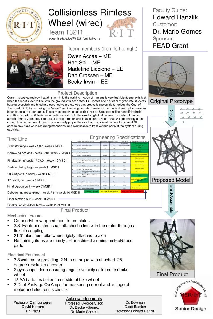
Collisionless Rimless Wheel (wired) Team 13211. Faculty Guide: Edward Hanzlik Customer: Dr. Mario Gomes Sponsor: FEAD Grant. edge.rit.edu/edge/P13211/public/Home. Team members (from left to right) Owen Accas – ME Hao Shi – ME Madeline Liccione – EE Dan Crossen – ME

E N D
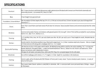
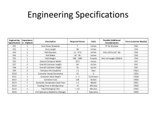
Collisionless Rimless Wheel (wired) Team 13211 Faculty Guide: Edward Hanzlik Customer: Dr. Mario Gomes Sponsor: FEAD Grant edge.rit.edu/edge/P13211/public/Home Team members (from left to right) Owen Accas – ME Hao Shi – ME Madeline Liccione – EE Dan Crossen – ME Becky Irwin – EE Project Description Current robot technology that aims to mimic the walking motion of humans is very inefficient; energy is lost when the robot's feet collide with the ground with each step. Dr. Gomes and his team of graduate students have successfully modeled and constructed a prototype that proves it is possible to reduce the Cost of Transport (CoT) by removing the "wheel" and involving periodic transfer of mechanical energy between an inner wheel and outer frame. The current prototype can walk down an 8 degree incline ramp if the initial condition is met; i.e. if the inner wheel is wound up to the exact angle that causes the system to move almost perfectly periodic. The task is to add a motor, and thus, control system, that will add energy at the correct time in the periodic arc to continuously propel the robot across a level surface for at least 40 consecutive trials while recording mechanical and electrical data from various parts of the system during each trial. Design Engineering Specifications Time Line Brainstorming – week 1 thru week 4 MSD I Narrowing designs – week 5 thru week 7 MSD I Finalization of design / CAD – week 10 MSD I Proposed Model Parts ordering begins – week 11 MSD I 90% of parts in hand – week 4 MSD II Original Prototype 1st prototype – week 5 MSD II Final Design built – week 7 MSD II On track for completion Not good/will not complete Good/completed Debugging / redesigning – week 7 thru week 10 MSD II Build/Assemble Final iteration built – week 10 MSD II Finalization of yellow items – week 11 of MSD II Final Product • Mechanical Frame • Carbon Fiber wrapped foam frame plates • 3/8” Hardened steel shaft attached in line with the motor through a flexible coupling • 21.5” aluminum bike wheel rigidly attached to axle • Remaining items are mainly self machined aluminum/steel/brass parts Final Product • Electrical Equipment • 3.8 watt motor providing .2 N-m of torque with attached .25 degree resolution encoder • 2 gyroscopes for measuring angular velocity of frame and bike wheel • 18 AA batteries bolted to outside of bike wheel • 2 Dual Package Op Amps for measuring current and voltage of motor and electronics circuits Professor Carl Lundgren David Herrera Dr. Patru Acknowledgements Professor George Slack Dr. Becker-Gomez Dr. Mario Gomes Dr. Bowman Geoff Bastion Professor Edward Hanzlik