Download
1 / 24
260 likes | 446 Vues
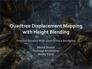
4 . 10. Displacement Mapping. Exploration of bump, parallax, relief and displacement mapping. Tangent Space. Overview of Tangent Space. Tangent Space. TBN Matrix. In order to understand bump mapping it is firstly necessary to understand tangent space.

E N D
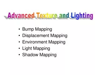
4.10.Displacement Mapping Exploration of bump, parallax, relief and displacement mapping
Tangent Space Overview of Tangent Space
Tangent Space TBN Matrix In order to understand bump mapping it is firstly necessary to understand tangent space. Common coordinate spaces (and transforms) are as shown opposite. The view matrix converts from world space to view space, with the projection matrix converting view eye space into clip space. After clip space, coordinates undergo perspective divide and a viewport transformation, ultimately resulting in “window coordinates”. Model Matrix View Matrix Projection Matrix
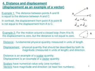
Tangent Space Tangent space is the coordinate space local to the surface of the model. For a single quad, tangent space is the coordinate space formed by the two tangent vectors along the S and T axis, and the surface normal.
Tangent Space A TBN matrix converts from object space to tangent space. It is build as: (where S and T are the tangents and N the normal). • Aside: TBN is short for: Tangent, Binormal, Normal, where Binormal is another name for the tangent (sometimes known, arguably more senisbly, as a bitangent).
Displacement Mapping Different forms of Displacement Mapping
Introduction to Bump Mapping Bump mapping is a technique which adds surface ‘roughness’, improving the visual fidelity of minute surface detail which would otherwise require a large number of polygons to model. A bump map is a form of texture that holds bump information. Commonly , a bump map stores a height field (e.g. A greyscale image where the brightness of each pixel holds the intended surface height) Bump mapping techniques operate by changing how a particular pixel is lit or textured based on the view angle and the stored height information.
Introduction to Bump Mapping Within standard rendering, the object’s geometric surface normal is calculated for each pixel to be rendered. This normal controls how light interacts with the object (e.g. within Phong shading). A bump map can be used to calculate the surface normal of the height map, modifying the calculated normal and effecting how the pixel is lit. The height map may also be used to control which part of a diffuse texture is used to texture the pixel.
Introduction to Bump Mapping A range of different types of bump mapping algorithm exist. Normal mapping offers the most simple form of bump mapping technique. Parallax mapping offers a slightly more complex approach. Relief mapping (or parallax occlusion mapping) is a more complex form of parallax mapping using simple ray tracing. Displacement mapping is a more true form of bump mapping that modifies the position of vertices. Simple forms of bump mapping only perturb the surface normals. The more complex forms of bump mapping provide bumpy silhouettes and realistic shadows.
Normal Mapping A normal map holds (in the RGB channels) the X, Y and Z coordinate tangent space normals. The normal map is used to provide a more accurate per-pixel normal when calculating the intensity of the light on that surface. This provides the illusion of considerably more fine surface detail.
Parallax Mapping Parallax mapping (also called offset mapping) extends basic normal mapping and provides more apparent depth. There are several different types of parallax mapping, including: Offset and Offset with Limiting Iterative parallax Parallax occlusion Relief Cone step Steep parallax Basic parallax mapping (offset and iterative) is a single step process which does not take into account occlusion. Later extensions incorporate iterative approaches which permit occlusion and accurate silhouette rendering. However, it is only now that such approaches are becoming feasible on current hardware.
Parallax Mapping Parallax mapping changes the texture lookup coordinates by introducing a displacement based on the tangent space viewing angle and the height space value. At steeper view-angles, the texture coordinates are displaced more, giving the illusion of depth due to parallax effects as the view changes. Basic parallax mapping looks good on any relatively large surface viewed from non-oblique angles (e.g. walls and floors). It's not good for steep edges, because of the distortion
Relief Mapping / Parallax Occlusion Mapping Relief mapping is one name (also including steep parallax mapping and parallax occlusion mapping) for a class of algorithms that trace rays against a height field. The basic approach is to walk along a ray which has entered the height field's volume and find the first point of intersection with the height field.
Relief Mapping / Parallax Occlusion Mapping Various techniques have been proposed to speed up the ray trace by taking variable step sizes. Relief mapping is capable of providing surface self-occlusion, self-shadowing, view-motion parallax and silhouettes.
Explore the DirectX SDK Parallax Occlusion Mapping sample • Parallax Occlusion Mapping
Displacement Mapping Displacement mapping modifies the actual geometric position of points over a textured surface (typically along the surface normal). It provides self-occlusion, self-shadowing and silhouettes. However, it is also a costly mapping process as additional geometry must be introduced as part of an adaptive tessellation (increasing the number of rendered polygons) to produce a more highly detailed mesh.
Directed reading Directed Reading Directed reading regarding bump mapping
Directed reading: Bump Mapping Read Displacement Mapping on the GPU — State of the Art – for an excellent overview of different displacement mapping techniques (bump, parallax, displacement, etc.). Read Detailed Shape Representation with Parallax Mapping – for the initial formulation of parallax mapping Read ShaderX3 - Parallax Occlusion Mapping – for the initial formulation of parallax occlusion mapping Read Displacement Mapping – for coverage of true displacement mapping Directed reading
Directed reading: Bump Mapping For a selection of interesting papers on advanced approaches for parallax mapping read: Prism Parallax Occlusion Mapping with Accurate Silhouette Generation Real-Time Relief Mapping on Arbitrary Polygonal Surfaces Relief Mapping of Non-Height-Field Surface Details Dynamic Parallax Occlusion Mapping with Approximate Soft Shadows GPU Gems 2 - Per-Pixel Displacement Mapping with Distance Functions GPU Gems 3 - Relaxed Cone Stepping for Relief Mapping Directed reading
Summary Today we explored: • Different types of bump/ displacement mapping. To do: • Read the directed reading • Think if you would like to provide bump / displacement mapping techniques within your project