Download
1 / 10
100 likes | 206 Vues
Overview. Maximum Δ T admissible at cooling system. T_1. T_1+0.5* Δ T. Stave. T_2. If T_2 – T_1 = 6 K, the maximum Δ T at the stave would be 0.5*(T_2-T_1) = 3 K In the prototypes tested up to now, Δ T in the water maximum was 3 K

E N D
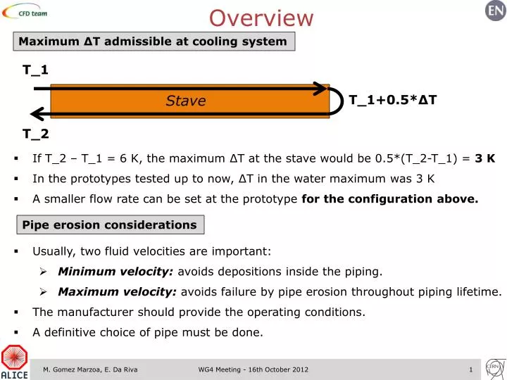
Overview Maximum ΔT admissible at cooling system T_1 T_1+0.5*ΔT Stave T_2 • If T_2 – T_1 = 6 K, the maximum ΔT at the stave would be 0.5*(T_2-T_1) = 3 K • In the prototypes tested up to now, ΔT in the water maximum was 3 K • A smaller flow rate can be set at the prototype for the configuration above. Pipe erosion considerations • Usually, two fluid velocities are important: • Minimum velocity: avoids depositions inside the piping. • Maximum velocity: avoids failure by pipe erosion throughout piping lifetime. • The manufacturer should provide the operating conditions. • A definitive choice of pipe must be done. WG4 Meeting - 16th October 2012
Overview Maximum ΔT admissible at cooling system T_1 T_1+0.5*ΔT Stave T_2 • If T_2 – T_1 = 6 K, the maximum ΔT at the stave would be 0.5*(T_2-T_1) = 3 K • In the prototypes tested up to now, ΔT in the water maximum was 3 K • A smaller flow rate can be set at the prototype for the configuration above. Pipe erosion considerations • Usually, two fluid velocities are important: • Minimum velocity: avoids depositions inside the piping. • Maximum velocity: avoids failure by pipe erosion throughout piping lifetime. • The manufacturer should provide the operating conditions. • A definitive choice of pipe must be done. To be done WG4 Meeting - 16th October 2012
Overview Piping diameter for two-phase cooling system • Based on results obtained with D08 prototype and C4F10, and using correlations to back up the ΔTSat for the experienced Δp. • For given mass flow rate -> max. ΔTSat-> max. Δp allowed -> Pipe Dmin • Pipe-refrigerant compatibility: • C4F10 is not compatible with the PTFE (Teflon) pipe that has been ordered to avoid the connection at the the turn of the cooling pipe. • Detector Cooling database provides information on this subject. Material budget considerations • Prototype thermal optimization done. • Precise calculation of the local and average material budget for the present and optimized prototypes would help optimizing from material budget viewpoint. • Estimation important for the prototypes at the outer layers. WG4 Meeting - 16th October 2012
Overview Piping diameter for two-phase cooling system • Based on results obtained with D08 prototype and C4F10, and using correlations to back up the ΔTSat for the experienced Δp. • For given mass flow rate -> max. ΔTSat-> max. Δp allowed -> Pipe Dmin • Pipe-refrigerant compatibility: • C4F10 is not compatible with the PTFE (Teflon) pipe that has been ordered to avoid the connection at the the turn of the cooling pipe. • Detector Cooling database provides information on this subject. To be done Material budget considerations • Prototype thermal optimization done. • Precise calculation of the local and average material budget for the present and optimized prototypes would help optimizing from material budget viewpoint. • Estimation important for the prototypes at the outer layers. To be done WG4 Meeting - 16th October 2012
ITS External Layers • Preliminary estimations: based on the High Thermal Conductivity Plate design. D-pipe?? • Parameters to define: D_pipe, plate thickness, material budget. WG4 Meeting - 16th October 2012
ITS External Layers Power dissipation Pipe diameter estimation WG4 Meeting - 16th October 2012
ITS External Layers Pressure drop estimation WG4 Meeting - 16th October 2012
ITS External Layers Mechanical constraints • Option A: stave is a full module. • Sag can be a problem: L4-5 -> 843 mm; L6-7 -> 1475 mm long • Manufacturing? • Option B: stave composed by multiple modules. • Need connections for piping and supports along the stave. • Bigger material budget? Leaks? • Mechanical constraints seem tighter than the cooling requirements. WG4 Meeting - 16th October 2012
DSF water tests Circuit status • By-pass made to increase the demand of water at our output and prevent pressure oscillations (needs optimization). • Pressure fluctuations at the inlet not suppressed so far: • Agree with other users of water circuit on a schedule? • Use independent plant (TRD Cuvee, ATLAS Julabo). Prototype tests: status • Wound-truss structure with 0.1 mm thick carbon fiber (D10): tests undergoing. • HTC Plate structure (D11): heater not glued yet • Similar to D06 prototype (performed under 30 °C) • Essential to fully understand and characterize the behavior of this solution. WG4 Meeting - 16th October 2012
DSF water tests Circuit status • By-pass made to increase the demand of water at our output and prevent pressure oscillations (needs optimization). • Pressure fluctuations at the inlet not suppressed so far: • Agree with other users of water circuit on a schedule? • Use independent plant (TRD Cuvee, ATLAS Julabo). Prototype tests: status • Wound-truss structure with 0.1 mm thick carbon fiber (D10): tests undergoing. • HTC Plate structure (D11): heater not glued yet • Similar to D06 prototype (performed under 30 °C) • Essential to fully understand and characterize the behavior of this solution. To be done WG4 Meeting - 16th October 2012