Download
1 / 37
450 likes | 1.36k Vues
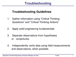
Furnace Troubleshooting. Combustion Service. Objectives : Good furnace troubleshooting requires enhanced skills from the servicer. Service Tips Induced draft furnace combustion process Combustion system service checks System effects on draft Flame detection - principles and service checks

E N D
Objectives : Good furnace troubleshooting requires enhanced skills from the servicer • Service Tips • Induced draft furnace combustion process • Combustion system service checks • System effects on draft • Flame detection - principles and service checks • Flame sensing variables
Service Tip • Use of diagnostic LED • 40” Furnace “book” (p.9)
Service Tip • Use of diagnostic LED (40” Furnace “book” (p.9) DON’T TOUCH THAT DIAL !!
WHITE-RODGERS Emerson Electric Co. WR MODEL 50A51 - 405 D340021P01 REPLACE WITH CNT 1308 FP MVH PS2 HLI TH GND R MV COM TR MVL PS1 GND HLO DIAGNOSTIC INDICATOR FLASHING SLOW NORMAL, NO CALL FOR HEAT FLASHING FAST NORMAL CALL FOR HEAT CONTINUOUS ON REPLACE CONTROL CONTINUOUS OFF CHECK POWER 2 FLASHES SYSTEM LOCKOUT (NO FLAME) 3 FLASHES PRESSURE SWITCH PROBLEM 4 FLASHES THERMAL PROTECTION DEVICE OPEN 5 FLASHES FLAME SENSED WITH GAS VALVE OFF REFER TO SERVICE INSTRUCTIONS FOR MORE INFORMATION W1W2 Y R G B Error Flash Codes
WR FP MVH PS2 HLI TH GND MV COM TR MVL PS1 GND HLO Error Flash Codes(See p. 9) WHITE-RODGERS Emerson Electric Co. MODEL 50A51 - 405 D340021P01 REPLACE WITH CNT 1308 DIAGNOSTIC INDICATOR FLASHING SLOW NORMAL, NO CALL FOR HEAT FLASHING FAST NORMAL CALL FOR HEAT CONTINUOUS ON REPLACE CONTROL CONTINUOUS OFF CHECK POWER 2 FLASHES SYSTEM LOCKOUT (NO FLAME) 3 FLASHES PRESSURE SWITCH PROBLEM 4 FLASHES THERMAL PROTECTION DEVICE OPEN 5 FLASHES FLAME SENSED WITH GAS VALVE OFF REFER TO SERVICE INSTRUCTIONS FOR MORE INFORMATION R W1W2 Y R G B
Pressure Switch Error • What can cause the Integrated Furnace Control to indicate a pressure switch error? (Flowchart on p. 51 of 40” Furnace “Book”)
INTEGRATED FURNACE CONTROL TR 6 TH 3 GAS VALVE 9 MV 2 1, 3 MV 12 4 PRESSURE SWITCH 5 FUSE LINK TCO PS 10 HLI 7 11 FUSE LINK TCO-B 1 HLO FP 2 FLAME SENSOR 8 GND G R C Y W Pressure SwitchSingle Stage
INTEGRATED FURNACE CONTROL TR 2 TH 7 GND 11 PRESSURE SWITCH 2ND STAGE PS2 8 GAS VALVE MVH 3 12 MVCOM 2 6 MVL 1 10 PRESSURE SWITCH 1ST STAGE GND 9 FUSE LINK TCO PSI 1 HLI 3 FUSE LINK TCO-B HLO 5 FP 4 FLAME SENSOR COM LO R G B W W Y CL HI 1 2 THERMOSTAT TWINNING Pressure SwitchTwo Stage
IGN 1 IND HI 2 IND. MTR. IND LO 3 IFC IND N 4 IGNITOR IGN N 5 PRESSURE SWITCH 1ST STAGE GND 9 FUSE LINK TCO PSI 1 HLI 3 FUSE LINK IFC TCO-B HLO 5 FP 4 FLAME SENSOR COM LO R G B W W Y CL HI 1 2 THERMOSTAT TWINNING Inducer Motor
Pressure Switch Error What can cause the integrated furnace control to indicate a pressure switch error? • Switch CLOSED when it should be OPEN • 24 VAC at “PS” too early (inducer not “energized) (See Flowchart on p.51 of 40” Furnace “Book”)
Pressure Switch Error What can cause the integrated furnace control to indicate a pressure switch error? • Switch OPEN when it should be CLOSED • No 24 VAC at “PS”, inducer circuit “energized” (See Flowchart on p.51 of 40” Furnace “Book”)
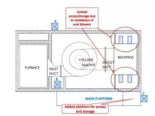
Pressure Switch Error Diagnostics • Vent Length • Draft/Vacuum Measurements • Electrical Checks • Factors Affecting Draft
MAXIMUM VENT LENGTH: MAXIMUM TOTAL EQUIVALENT FEET FOR VENT AND INLET AIR (See Notes) 2” PIPE & FITTINGS 2-1/2” PIPE & FITTINGS 3” PIPE & FITTINGS MODEL *UX040C924 *UX060C936 *UX080C942 *UX100C948 *UX100C960 *UX120C960 60 60 60 30 30 N/A 80 80 80 80 80 15 100 100 100 100 100 60 NOTES: First Letter may be “A” or “T” 1. DO NOT MIX PIPE DIAMETERS IN THE SAME LENGTH OF PIPE OUTSIDE THE FURNACE CABINET (except adapters at top of furnace). 2. MAXIMUM PIPE LENGTHS MUST NOT BE EXCEEDED 3. One 90 o elbow is equivalent to 10 ‘ of 3 “ pipe 71/2’ of 21/2” pipe, & 5’ of 2” pipe. Two 45o elbows equal one 90o elbow. 4. The termination tee or bend must be included in the total number of elbows. The BAYVENT100A termination is equal to 5 equivalent feet of pipe. The BAYVENT200A is 0 equivalent feet. 5. Pipe adapters are field supplied. Determining Total Vent LengthsSee p. 9 of Installer Guide 18-CD19D6-5
FIELD SUPPLIED TUBE & TEE SECTION Combustion Air Pressure Switch
Examine the effects of system variations on draft • Vent Length • Blockages • Wind • Gas Input • Airflow
PRESSURE DIFFERENTIAL SWITCH BURNER BOX PRIMARY HEAT EXCHANGER INLET PIPE TRANSFER TUBE RECOUP CELL FLUE COLLECTOR BOX Vacuum / Draft Pathway INDUCED DRAFT BLOWER
Effects of Low System Airflow on Internal Vacuum Hot furnace Means hot flue gases Hot flue gases expand - take up more space Expanding flue gases raise pressure in furnace
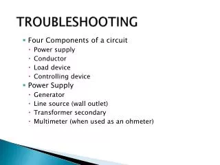
Flame RectificationRef p.25 of 40” Furnace “Book” • Remember Ohm’s Law E = I X R
Basic Electrical Circuit SOURCE - + CONDUCTOR CONTROL LOAD
+ + + Applied AC voltage - - Alternating Current Sine Wave
Flame Rectification circuit What devices are used for electrodes? • Flame rod • Burner
Flame Rectification Circuit • Voltage Source: Ignition Control • “Load”: flame sensing circuit inside the control • Conductors: wires, and electrodes already identified. • “Switch”? • The flame completes the circuit.
Flame Sense Circuit • One electrode is larger than the other causing electron flow to be greater in one direction than in the other. • Compare the burner size to the flame rod size.
Flame Sensing - Service • Measuring outputs • Measuring inputs • Circuit integrity checks • Polarity • Grounding method / continuity
5a + 0 - + FP GND _ Current flow when flame rod is positive
1a + 0 - _ FP GND + Current flow when flame rod is negative
Effective Flame Signal + + a Effect = 4a pulsating DC Applied AC voltage - - a
Flame Rectification Circuit Remember Ohm’s Law ? What happens in a circuit if resistance increases and voltage stays the same? What can affect the resistance in the circuit? What else can affect the flame signal?
Increased circuit resistances • Burner oxidation • Non-secure burner • Flame “lift off” • Loose wire connections • Contaminated flame sensor • Faulty grounds • No grounds • Reverse polarity
DC Current vs. AC Current VALVE DROPOUT IS IN AC MICROAMPS
DC Current vs. AC Current 50A50 1 STG CONTROL
Flame Sensing - Variables • Remember Ohms Law E=I x R • Watch that resistance • Too little DC = too bad • Too much AC = too bad • Grounded flame sensor • Look out for noise!
Question Name something which can cause a “2 flash” lockout which has not yet been discussed. Answer: 1) No gas available - check supply 2) Multiple recycles caused by other faults (ie: pressure switch trips) (See p.10)